DM240011 Microchip Technology, DM240011 Datasheet - Page 12
DM240011
Manufacturer Part Number
DM240011
Description
KIT STARTER MPLAB FOR PIC24F MCU
Manufacturer
Microchip Technology
Series
MPLAB®r
Type
MCUr
Datasheet
1.DM240011.pdf
(42 pages)
Specifications of DM240011
Contents
Board, Cable, CD
Processor To Be Evaluated
PIC24F
Data Bus Width
16 bit
Interface Type
USB
Silicon Manufacturer
Microchip
Core Architecture
PIC
Core Sub-architecture
PIC24
Silicon Core Number
PIC24F
Silicon Family Name
PIC24FJxxGBxxx
Kit Contents
Board Cables CD Docs
Lead Free Status / RoHS Status
Lead free / RoHS Compliant
For Use With/related Products
PIC24F
Lead Free Status / Rohs Status
Lead free / RoHS Compliant
Available stocks
Company
Part Number
Manufacturer
Quantity
Price
Company:

Part Number:
DM240011
Manufacturer:
Microchip Technology
Quantity:
135
Company:
Part Number:
DM240011
Manufacturer:
MICROCHIP
Quantity:
12 000


MPLAB Starter Kit for PIC24F User’s Guide
1.3
DS51725A-page 8
INITIAL BOARD SETUP
With its pre-installed demo application, the MPLAB Starter Kit for PIC24F is designed
to be used straight out of the box. Except for a single connection to a computer, no
additional hardware or configuration is necessary.
1.3.1
Before connecting the starter kit to any computer for the first time, it is very important
to install the accompanying software on the MPLAB Starter Kit for PIC24F CD first. This
ensures that the proper USB drivers for communicating with the starter kit
programmer/debugger are installed and ready to recognize the board.
To install the software and driver, insert the starter kit CD into the CD-ROM drive. The
installation process starts automatically. The process pauses for user responses to
accept the Microchip software licenses and to confirm the installation directories;
respond appropriately.
1.3.2
Once the starter kit software is installed, connect the provided USB cable (A to mini-B)
to any available USB port on the PC or powered hub, then to the starter kit at the mini-B
receptacle, J1, on the programmer/debugger side of the board (Figure 1-1). The PC
USB connection provides communication and power to the board. A USB Flash drive,
used for portions of the demo application, may be connected to the starter kit at any
time.
If the cable is connected correctly, the green Power and Target Power LEDs (D2 and
D4) are lit. LED1 displays a reversed raster and start-up screen, while the tri-color LED
cycles through a sequence of colors. After this power-on sequence, LED1 will display
the “PIC24F Starter Kit” main menu.
At the same time, a sequence of pop-up balloons in the system tray (lower right of
desktop) should appear, stating that (1) new hardware has been found, (2) drivers are
being installed and (3) the new hardware is ready for use. If you do not see these
messages and the starter kit does not work, try unplugging and reconnecting the USB.
If this does not work, refer to Section 4.8 “Troubleshooting”.
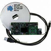
FIGURE 1-1:
A to mini-B USB Cable
Installing the Software
Connecting the Hardware
STARTER KIT SETUP
M
Starter Kit
© 2008 Microchip Technology Inc.
USB Flash Drive
(not included)
Related parts for DM240011
Image
Part Number
Description
Manufacturer
Datasheet
Request
R

Part Number:
Description:
Manufacturer:
Microchip Technology Inc.
Datasheet:
Part Number:
Description:
Manufacturer:
Microchip Technology Inc.
Datasheet:
Part Number:
Description:
Manufacturer:
Microchip Technology Inc.
Datasheet:
Part Number:
Description:
Manufacturer:
Microchip Technology Inc.
Datasheet:
Part Number:
Description:
Manufacturer:
Microchip Technology Inc.
Datasheet:
Part Number:
Description:
Manufacturer:
Microchip Technology Inc.
Datasheet:
Part Number:
Description:
Manufacturer:
Microchip Technology Inc.
Datasheet:
Part Number:
Description:
Manufacturer:
Microchip Technology Inc.
Datasheet: