DM240011 Microchip Technology, DM240011 Datasheet - Page 16
DM240011
Manufacturer Part Number
DM240011
Description
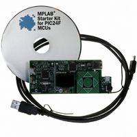
KIT STARTER MPLAB FOR PIC24F MCU
Manufacturer
Microchip Technology
Series
MPLAB®r
Type
MCUr
Datasheet
1.DM240011.pdf
(42 pages)
Specifications of DM240011
Contents
Board, Cable, CD
Processor To Be Evaluated
PIC24F
Data Bus Width
16 bit
Interface Type
USB
Silicon Manufacturer
Microchip
Core Architecture
PIC
Core Sub-architecture
PIC24
Silicon Core Number
PIC24F
Silicon Family Name
PIC24FJxxGBxxx
Kit Contents
Board Cables CD Docs
Lead Free Status / RoHS Status
Lead free / RoHS Compliant
For Use With/related Products
PIC24F
Lead Free Status / Rohs Status
Lead free / RoHS Compliant
Available stocks
Company
Part Number
Manufacturer
Quantity
Price
Company:

Part Number:
DM240011
Manufacturer:
Microchip Technology
Quantity:
135
Company:
Part Number:
DM240011
Manufacturer:
MICROCHIP
Quantity:
12 000


MPLAB Starter Kit for PIC24F User’s Guide
DS51725A-page 12
2.2.2
This demo shows the ability of the PIC24F microcontroller to function as an embedded
host by reading data from a USB Flash drive. To access the demo, select “Flash Drive”
from the main menu.
If a USB Flash drive with files is plugged in to the USB A-receptacle (J4), the display
shows the drive volume name and top level file structure in a list box (Figure 2-5). Long
file and directory names are truncated according to earlier Microsoft 8+3 file system
conventions (e.g., Longfilename.doc would be truncated as LONGFI~1.doc). Use
the up/down arrow keys to scroll through the directory.
Subdirectories are indicated by names with a folder symbol next to them, and are
opened by pressing the center touch pad. To move up a directory level, select the “..”
entry at the top of the menu window and press the center touch pad.
If a Flash drive is not present, the display shows an empty menu window and the mes-
sage “Insert media”. If the Flash drive has no content, the display will show only the
drive volume name.
To exit the Flash Drive demo and return to the main menu, press the left arrow touch pad.
FIGURE 2-5:
2.2.3
As an additional demonstration of the application’s ability to interact with users in real
time, the Data Graphing demo shows the capture and conversion of analog data to
graphic information as it happens. In this demo, the input from the potentiometer (R44)
is converted by the microcontroller’s A/D converter to digital information, and plotted as
a time vs. amplitude graph on the OLED display.
To access this demo, select “Demos” from the main menu, then “Graph” from the
“Demonstrations” menu. A horizontally scrolling graph appears with a solid line indicat-
ing the current position of the potentiometer. Turning the potentiometer through its
entire range changes the y-coordinate of the line in real time. At its default setting, the
application updates the value from the potentiometer every 100 ms; each time axis
division represents approximately 2 seconds. To increase or decrease the graph’s
update rate, press the right or left arrow touch pads, respectively.
To exit the demo and return to the main menu, press the center touch pad.
FIGURE 2-6:
i
Insert media...
USB Flash Drive Interface (USB Embedded Host)
Real-Time Data Graphing (A/D and Display Multitasking)
TYPICAL DISPLAYS FOR THE FLASH DRIVE INTERFACE
DATA GRAPHING DISPLAY
i
Potentiometer Graph
i
\THUMB
CAPTURE.CSV
.\SUBDIR~1
.\TRANSFER
© 2008 Microchip Technology Inc.
Related parts for DM240011
Image
Part Number
Description
Manufacturer
Datasheet
Request
R

Part Number:
Description:
Manufacturer:
Microchip Technology Inc.
Datasheet:
Part Number:
Description:
Manufacturer:
Microchip Technology Inc.
Datasheet:
Part Number:
Description:
Manufacturer:
Microchip Technology Inc.
Datasheet:
Part Number:
Description:
Manufacturer:
Microchip Technology Inc.
Datasheet:
Part Number:
Description:
Manufacturer:
Microchip Technology Inc.
Datasheet:
Part Number:
Description:
Manufacturer:
Microchip Technology Inc.
Datasheet:
Part Number:
Description:
Manufacturer:
Microchip Technology Inc.
Datasheet:
Part Number:
Description:
Manufacturer:
Microchip Technology Inc.
Datasheet: