DM180021 Microchip Technology, DM180021 Datasheet - Page 30
DM180021
Manufacturer Part Number
DM180021
Description
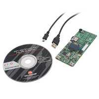
KIT STARTER MPLAB FOR PIC18F MCU
Manufacturer
Microchip Technology
Series
MPLAB®r
Type
MCUr
Specifications of DM180021
Contents
Board, Cable, CD
Processor To Be Evaluated
PIC18F46J50
Processor Series
PIC18F
Interface Type
SPI
Operating Supply Voltage
3.3 V
Silicon Manufacturer
Microchip
Core Architecture
PIC
Core Sub-architecture
PIC18
Silicon Core Number
PIC18F
Silicon Family Name
PIC18F4xxx
Kit Contents
Board
Lead Free Status / RoHS Status
Lead free / RoHS Compliant
For Use With/related Products
PIC18Fxxxx
Lead Free Status / Rohs Status
Lead free / RoHS Compliant
Available stocks
Company
Part Number
Manufacturer
Quantity
Price
Company:

Part Number:
DM180021
Manufacturer:
Microchip Technology
Quantity:
135
Company:
Part Number:
DM180021
Manufacturer:
MICROCHIP
Quantity:
12 000


MPLAB Starter Kit for PIC18F User’s Guide
TABLE 4-1:
DS51852A-page 26
Ref
D1
D2
D3
D4
D5
D6
PIC18F67J50 Microcontroller (U1)
mini-B USB Receptacle (J2)
Debugger/Programmer Clock Crystal (Y1)
25LC010A Serial EEPROM (U2)
Debug LED (D2)
Power LED (D3)
PIC18F STARTER KIT COMPONENT DESCRIPTIONS
Debug/Programmer Component
4.3.1
The components listed here (in order of their reference tags in Figure 4-3) are the key
components of the programmer/debugger side of the starter kit:
D1. PIC18F67J50 Microcontroller (U1): Controls the programming/debugging
D2. mini-B USB Receptacle (J2): Provides system power and bidirectional
D3. Debugger/Programmer Clock Crystal (Y1): Provides an accurate 12 MHz
D4. 25LC010A Serial EEPROM (U2): Store the starter kit’s serial number and
D5. Target Power LED (D2): When lit, indicates that power is being supplied to the
D6. Debug LED (D3): When lit, indicates that the starter kit is operating in
4.3.2
The components listed here (in order of their reference tags in Figure 4-3) are the key
components of the application side of the starter kit:
A1. PIC18F46J50 Microcontroller (U3): This provides the processing power for
A2. OLED Display (LED1): A 128 x 64 pixel, monochrome organic LED array
A3. MicroSD Card Socket (J5): A standard socket that is read and write compatible
operations of the target PIC18F46J50 microcontroller. It also provides the
12 MHz clock for the application side of the microcontroller.
communication between the host PC and starter kit.
frequency reference for the PIC18F67J50 microcontroller for stable USB
operations in Programming and Debugging modes. The PIC18F67J50 also
uses this to generate a second 12 MHz clock for use by the PIC18F46J50
microcontroller.
debug control information.
starter kit from V
Programming or Debug mode.
the demo applications and application development on the starter kit. The micro-
controller features 64 Kbytes of Flash program memory and 3.7 Kbytes RAM.
The demo application uses an external 12 MHz signal from the programmer side
as clock source. Custom applications that do not use the USB module may also
use the microcontroller’s on-chip FRC oscillator as a clock source. (USB appli-
cations must use the 12 MHz programmer clock source, as the tolerance of the
FRC oscillator exceeds USB specifications.)
provides a wide range of graphics and alphanumeric display options.
with all MicroSD cards. The socket and the application side of the
microcontroller communicate over an SPI interface.
Programmer/Debugger Components
Application Components
BUS
, either from the Application or Programmer/Debugger side.
A10
A11
Ref
A2
A3
A4
A5
A1
A6
A7
A8
A9
PIC18F46J50 Microcontroller (U3)
OLED Display (LED1)
MicroSD™ Card Socket (J5)
BMA150 Acceleration Sensor (U6)
Capacitive Touch Pad (S1)
mini-B USB (Peripheral) Receptacle (J3)
Potentiometer (R24)
Bootloader Reset Push Button Switch (S1)
MCP1727 Voltage Regulator (U5)
Soft Start Circuit (Q1)
OLED Voltage Boost Cicuitry
Application Component
© 2009 Microchip Technology Inc.
Related parts for DM180021
Image
Part Number
Description
Manufacturer
Datasheet
Request
R

Part Number:
Description:
Manufacturer:
Microchip Technology Inc.
Datasheet:
Part Number:
Description:
Manufacturer:
Microchip Technology Inc.
Datasheet:
Part Number:
Description:
Manufacturer:
Microchip Technology Inc.
Datasheet:
Part Number:
Description:
Manufacturer:
Microchip Technology Inc.
Datasheet:
Part Number:
Description:
Manufacturer:
Microchip Technology Inc.
Datasheet:
Part Number:
Description:
Manufacturer:
Microchip Technology Inc.
Datasheet:
Part Number:
Description:
Manufacturer:
Microchip Technology Inc.
Datasheet:
Part Number:
Description:
Manufacturer:
Microchip Technology Inc.
Datasheet: