AT91SAM7L-STK Atmel, AT91SAM7L-STK Datasheet
AT91SAM7L-STK
Specifications of AT91SAM7L-STK
AT91SAM7L-EK
Available stocks


Related parts for AT91SAM7L-STK


AT91SAM7L-STK Summary of contents
Page 1
... AT91SAM7L-STK Rev. A Starter Kit .................................................................................................................... User Guide 6409A–ATARM–30-Jun-08 ...
Page 2
... AT91SAM7L-STK Rev. A Starter Kit User Guide ...
Page 3
... Table of Contents Section 1 Overview .................................................................................................................... 1-1 1.1 Scope................................................................................................................................. 1-1 1.2 Deliverables ...................................................................................................................... 1-1 1.3 The AT91SAM7L-STK Rev. A Starter Board ..................................................................... 1-1 Section 2 Setting Up the AT91SAM7L-STK Rev. A Board......................................................... 2-1 2.1 Electrostatic Warning ......................................................................................................... 2-1 2.2 Requirements..................................................................................................................... 2-1 2.3 Layout ................................................................................................................................ 2-2 2.4 Powering Up the Board...................................................................................................... 2-2 2.5 Getting Started ...
Page 4
... Table of Contents (Continued) 6.1 Q1 Footprint Incorrect ........................................................................................................ 6-1 6.2 MAX3318 Control Pull-ups................................................................................................. 6-2 Section 7 Revision History ......................................................................................................... 7-1 ii 6409A–ATARM–30-Jun-08 AT91SAM7L-STK Rev. A Starter Kit User Guide ...
Page 5
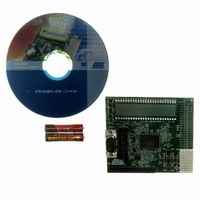
... Scope The AT91SAM7L-STK rev.A starter kit enables evaluation capabilities and code development of applica- tions running on an AT91SAM7L64/128. This guide focuses on the AT91SAM7L-STK rev.A board as an evaluation platform. 1.2 Deliverables The AT91SAM7L-STK rev.A package contains the following items: An AT91SAM7L-STK rev.A board Two AAA batteries 1 ...
Page 6
... Electrostatic Warning The AT91SAM7L-STK rev.A starter board is shipped in a protective anti-static package. The board must not be subjected to high electrostatic potentials. A grounding strap or similar protective device should be worn when handling the board. Avoid touching the component pins or any other metallic element. ...
Page 7
... Layout Figure 2-1. AT91SAM7L-STK Rev. A Board Layout 2.4 Powering Up the Board The AT91SAM7L-STK rev.A requires 3.0V (2.2V-3.6V) DC input. The power is supplied to the board via 2 AAA batteries or 3.0V VCC pads. 2.5 Getting Started Please refer to the on getting started with the AT91SAM7L-STK rev.A. ...
Page 8
... AT91SAM7L-STK Rev. A Starter Kit User Guide SHEET 2 Interfaces '%*8 PC[0..29] Interfaces SHEET 4 Processor AD[0..3] AD[0..3] PA[0..25] PA[0..25] PB[0..23] PB[0..23] PC[0..29] PC[0..29] ERASE Processor SHEET 3 LCD, KBD AD[0..3] AD[0..3] PA[0..25] PA[0..25] PB[0..23] PB[0..23] PC[0..29] PC[0..29] ERASE LCD, KBD Setting Up the AT91SAM7L-STK Rev. A Board 6409A–ATARM–30-Jun-08 2-3 ...
Page 9
... Handles Fast Start Up • Advanced Interrupt Controller (AIC) – Individually Maskable, Eight-level Priority, Vectored Interrupt Sources – Two External Interrupt Sources and One Fast Interrupt Source, Spurious Interrupt Protected AT91SAM7L-STK Rev. A Starter Kit User Guide ® ® ® ARM Thumb Processor ™ ...
Page 10
... Zero-power Power-on Reset and Brownout Detector, Fully Programmable • Fully Static Operation MHz at 85°C • Available in a 128-lead LQFP Green and a 144-ball LFBGA Green Package 3-2 6409A–ATARM–30-Jun-08 ® Infrared Modulation/Demodulation ® Two-wire EEPROMs and I AT91SAM7L-STK Rev. A Starter Kit User Guide 2 C compatible ...
Page 11
... SEG00-SEG39 COM0-COM9 RXD0 TXD0 SCK0 RTS0 CTS0 RXD1 TXD1 SCK1 RTS1 CTS1 DCD1 DSR1 DTR1 RI1 AT91SAM7L-STK Rev. A Starter Kit User Guide ICE ARM7TDMI JTAG SCAN Processor System Controller 2 MHz RCOSC AIC Memory Controller PLL PMC Embedded Address Flash Decoder OSC ...
Page 12
... One Serial interface (DBGU COM Port) via RS-232 DB9 male socket 3.10 Expansion Slot One ZIGBEE expansion connector for Atmel AT86RF230 adaptor All PIOC signals of the AT91SAM7L64/128 are routed to peripheral extension connector (J6). This allows the developer to add external hardware components or boards. 3-4 6409A–ATARM–30-Jun-08 AT91SAM7L-STK Rev. A Starter Kit User Guide ...
Page 13
... PA14 PA15 PA16 PA17 PA18 PA19 PA20 PA21 PA22 PA23 PA24 PA25 AT91SAM7L-STK Rev. A Starter Kit User Guide Peripheral Usage Segment LCD PANEL COM0 Segment LCD PANEL COM1 Segment LCD PANEL COM2 Segment LCD PANEL COM3 Segment LCD PANEL COM4 Segment LCD PANEL ...
Page 14
... Segment LCD PANEL SEG38 Segment LCD PANEL SEG39 Segment LCD PANEL COM6 Segment LCD PANEL COM7 Segment LCD PANEL COM8 Segment LCD PANEL COM9 AT91SAM7L-STK Rev. A Starter Kit User Guide Powered by VDDIO2 VDDIO2 VDDIO2 VDDIO2 VDDIO2 VDDIO2 VDDIO2 VDDIO2 VDDIO2 VDDIO2 ...
Page 15
... RTS0 FIQ PC27 NPCS2 IRQ0 PC28 SCK1 PWM0 PC29 RTS1 PWM1 AT91SAM7L-STK Rev. A Starter Kit User Guide Peripheral Usage User’s Input Buttons OK User’s Input Buttons UP User’s Input Buttons RIGHT User’s Input Buttons DOWN User’s Input Buttons ...
Page 16
... Configuration Straps Table 4-1 gives details of configuration straps on the AT91SAM7L-STK rev. A starter board and their default settings. Table 4-1. Designation J6 pins 39-40 J8 SD1 SD2 SD3 SD4 R20 TP1 TP2 TP3 TP4 TP5 TP6 TP7 TP8 TP9 TP10 Notes: 1. This jumper is used to erase and reinitialize the internal flash content and some of the NVM bits. ...
Page 17
... This section contains the following schematics: Top Level Interfaces LCD, KBD Processor AT91SAM7L-STK Rev. A Starter Kit User Guide Section 5 Schematics 5-1 6409A–ATARM–30-Jun-08 ...
Page 18
... VER. VER. VER. SCALE SCALE SCALE REV. REV. REV. AT91SAM7L-STK AT91SAM7L-STK AT91SAM7L-STK 1/1 1/1 1 Top level Top level Top level This agreement is our property. Reproduction and publication without our written authorization shall expose offender to legal proceedings. This agreement is our property. Reproduction and publication without our written authorization shall expose offender to legal proceedings. ...
Page 19
... NOT POPULATED NOT POPULATED GND AT91SAM7L-STK AT91SAM7L-STK AT91SAM7L-STK Interfaces Interfaces Interfaces This agreement is our property. Reproduction and publication without our written authorization shall expose offender to legal proceedings. This agreement is our property. Reproduction and publication without our written authorization shall expose offender to legal proceedings. ...
Page 20
... JS1 JS1 GND AT91SAM7L-STK AT91SAM7L-STK AT91SAM7L-STK LCD, KBD LCD, KBD LCD, KBD This agreement is our property. Reproduction and publication without our written authorization shall expose offender to legal proceedings. This agreement is our property. Reproduction and publication without our written authorization shall expose offender to legal proceedings. ...
Page 21
... SOLDER DROP 3 pins 3 SD4 SD4 AT91SAM7L-STK AT91SAM7L-STK AT91SAM7L-STK GND Processor Processor Processor This agreement is our property. Reproduction and publication without our written authorization shall expose offender to legal proceedings. This agreement is our property. Reproduction and publication without our written authorization shall expose offender to legal proceedings. ...
Page 22
... Remove R1, R2 and R3 and add a 10M Ω pull-down resistor on PC7. This allows to Force OFF the MAX3318 when the AT91SAM7L128 enters OFF mode and to turn it on when the AT91SAM7L128 wakes up. The user can save power consumption by driving PC7 connected to the FORCEOFF pin of the MAX3318. AT91SAM7L-STK Rev. A Starter Kit User Guide Section 6 Errata 6-1 ...
Page 23
... Doc Rev Comments 6409A First issue. AT91SAM7L-STK Rev. A Starter Kit User Guide Section 7 Revision History Change Request Ref. 7-1 6409A–ATARM–30-Jun-08 ...
Page 24
... Disclaimer: The information in this document is provided in connection with Atmel products. No license, express or implied, by estoppel or otherwise, to any intellectual property right is granted by this document or in connection with the sale of Atmel products. EXCEPT AS SET FORTH IN ATMEL’S TERMS AND CONDI- TIONS OF SALE LOCATED ON ATMEL’S WEB SITE, ATMEL ASSUMES NO LIABILITY WHATSOEVER AND DISCLAIMS ANY EXPRESS, IMPLIED OR STATUTORY WARRANTY RELATING TO ITS PRODUCTS INCLUDING, BUT NOT LIMITED TO, THE IMPLIED WARRANTY OF MERCHANTABILITY, FITNESS FOR A PARTICULAR PURPOSE, OR NON-INFRINGEMENT ...