DM163030 Microchip Technology, DM163030 Datasheet - Page 48
DM163030
Manufacturer Part Number
DM163030
Description
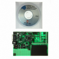
KIT DEV PICDEM LCD2
Manufacturer
Microchip Technology
Series
PICDEM™r
Type
MCUr
Specifications of DM163030
Contents
Evaluation Board
Processor To Be Evaluated
PIC18F85J90
Interface Type
RS-232
Lead Free Status / RoHS Status
Lead free / RoHS Compliant
For Use With/related Products
PIC18F8493
Lead Free Status / Rohs Status
Lead free / RoHS Compliant
Available stocks
Company
Part Number
Manufacturer
Quantity
Price
Company:

Part Number:
DM163030
Manufacturer:
MICROCHIP
Quantity:
12 000


PICDEM™ LCD 2 Demonstration Kit User’s Guide
A.11 TEMPERATURE SENSOR
A.12 SWITCHES
A.13 ICD CONNECTOR
DS51662C-page 48
A 10 kTC thermistor (R11) is provided to sense the temperature. It is connected to
AN1 (RA1) through the jumper, JP5. An optional unpopulated TC77-based circuit is
provided to read the temperature serially using the USART module. The jumpers, JP15
and JP16, are to be connected and RA1 of U1A should be made digital to be used to
enable TC77.
Four switches provide the following functions for digital I/Os:
• S1 – Active-low switch connected to RB6.
• S2 – Active-low switch connected to RB6 and RB7.
• S3 – Active-low switch connected to RB6, RB7 and RA6.
• S4 – Active-low switch connected to RB6, RB7, RA6 and RA7.
For this type of sensing, the jumpers, JP1, JP2, JP6, JP18, JP19, JP9 and JP10,
should be connected and the potentiometer should be connected to AN0 through J11.
Sensing should be done in the sequence, S1, S2, S3 and S4, only. Individual switch
sensing is not allowed.
Additionally, the four switches provide the following functions for analog input (AN0):
• S1 – AN0 will be approximately at V
• S2 – AN0 will be approximately at V
• S3 – AN0 will be approximately at V
• S4 – AN0 will be approximately at V
For this type of sensing, the jumpers, JP1, JP2, JP6, JP18 and JP19, should not be
connected and the SWT should be connected to AN0 through J11.
By way of the modular connector (J37), the MPLAB ICD 2 can be connected for
low-cost debugging. The ICD connector utilizes RB6/PGC and RB7/PGD of the
microcontrollers for in-circuit debugging.
Note 1:
2:
For the PIC18F85J90 and PIC18F87J90 PIM, the RA2 pin is connected
to RA1 of U1A and AN2 is used instead of AN1.
For the PIC18F8490, PIC16F/LF/1946/7, PIC16F946, and PIC16F917
PIMs, the RA1 pin is connected to RA1 of U1A.
CC
CC
CC
CC
/2.
/3.
/5.2.
/7.7.
2010 Microchip Technology Inc.
Related parts for DM163030
Image
Part Number
Description
Manufacturer
Datasheet
Request
R

Part Number:
Description:
Manufacturer:
Microchip Technology Inc.
Datasheet:
Part Number:
Description:
Manufacturer:
Microchip Technology Inc.
Datasheet:
Part Number:
Description:
Manufacturer:
Microchip Technology Inc.
Datasheet:
Part Number:
Description:
Manufacturer:
Microchip Technology Inc.
Datasheet:
Part Number:
Description:
Manufacturer:
Microchip Technology Inc.
Datasheet:
Part Number:
Description:
Manufacturer:
Microchip Technology Inc.
Datasheet:
Part Number:
Description:
Manufacturer:
Microchip Technology Inc.
Datasheet:
Part Number:
Description:
Manufacturer:
Microchip Technology Inc.
Datasheet: