AT91SAM7A3-EK Atmel, AT91SAM7A3-EK Datasheet
AT91SAM7A3-EK
Specifications of AT91SAM7A3-EK


Related parts for AT91SAM7A3-EK


AT91SAM7A3-EK Summary of contents
Page 1
... AT91SAM7A3-EK Evaluation Board .............................................................................................. User Guide ...
Page 2
... Table of Contents Section 1 Overview............................................................................................... 1-1 1.1 Scope........................................................................................................1-1 1.2 Deliverables ..............................................................................................1-1 1.3 The AT91SAM7A3-EK Evaluation Board..................................................1-1 Section 2 Setting Up the AT91SAM7A3-EK Evaluation Board............................. 2-1 2.1 Electrostatic Warning ................................................................................2-1 2.2 Requirements............................................................................................2-1 2.3 Layout .......................................................................................................2-2 2.4 Powering Up the Board .............................................................................2-3 2.5 Backup Power Supply ...............................................................................2-3 2 ...
Page 3
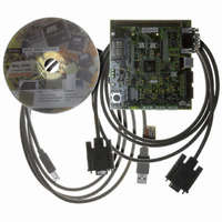
... AT91SAM7A3-EK Evaluation Board User Guide The AT91SAM7A3-EK evaluation kit enables evaluation capabilities and code develop- ment of applications running on an AT91SAM7A3. This guide focuses on the AT91SAM7A3-EK board as an evaluation platform. The AT91SAM7A3-EK package contains the following items AT91SAM7A3-EK board ! one A/B-type USB cable ...
Page 4
... Overview 1-2 6165C–ATARM–26-Jun-06 AT91SAM7A3-EK Evaluation Board User Guide ...
Page 5
... The board must not be subjected to high electrostatic potentials. A grounding strap or similar protective device should be worn when handling the board. Avoid touching the component pins or any other metallic element. In order to set up the AT91SAM7A3-EK evaluation board, the following items are required: ! the AT91SAM7A3-EK evaluation board itself ...
Page 6
... Setting Up the AT91SAM7A3-EK Evaluation Board 2.3 Layout Figure 2-1. Top Level Layout 2-2 6165C–ATARM–26-Jun-06 AT91SAM7A3-EK Evaluation Board User Guide ...
Page 7
... Refer to Table 4-1. The AT91SAM7A3-EK evaluation board is delivered with a DVD-ROM containing all necessary information and step-by-step procedures for working with the most common development tool chains. Please refer to this DVD-ROM the Atmel web site, http://www.atmel.com/products/AT91/, for the most up-to-date information on getting started with the AT91SAM7A3-EK ...
Page 8
... Setting Up the AT91SAM7A3-EK Evaluation Board 2.7 AT91SAM7A3-EK Block Diagram Figure 2-2. Block Diagram VBUS IN OUT 3.3V 3V3 S6 S6 nSHUTDOWN YELLOW YELLOW POWER LED PIO S7 S7 LIGHTED WHEN POWER ON J13 J13 VDD1V8 VDDPLL J14 J14 SYSTEM CONTROLLER XOUT XIN J26 J26 EXT CLK INPUT ...
Page 9
... AT91SAM7A3 Microcontroller AT91SAM7A3-EK Evaluation Board User Guide ® ! Incorporates the ARM7TDMI – High-performance 32-bit RISC Architecture – High-density 16-bit Instruction Set – Leader in MIPS/Watt ! Embedded ICE In-circuit Emulation, Debug Communication Channel Support ! 256 Kbytes of Internal High-speed Flash, Organized in 1024 Pages of 256 Bytes – ...
Page 10
... Programmable Data Length, Four External Peripheral Chip Selects ! Three 3-channel 16-bit Timer/Counters (TC) – Three External Clock Inputs, Two Multi-purpose I/O Pins per Channel – Double PWM Generation, Capture/Waveform Mode, Up/Down Capability ® Infrared Modulation/Demodulation AT91SAM7A3-EK Evaluation Board User Guide ...
Page 11
... AT91SAM7A3-EK Evaluation Board User Guide ! Two Synchronous Serial Controllers (SSC) – Independent Clock and Frame Sync Signals for Each Receiver and Transmitter – I²S Analog Interface Support, Time Division Multiplex Support – High-speed Continuous Data Stream Capabilities with 32-bit Data Transfer ! One Two-wire Interface (TWI) – ...
Page 12
... PDC PDC TC0 TC1 TC2 PDC PDC Timer Counter PDC TC3 TC4 TC5 Timer Counter PDC TC6 TC7 TC8 AT91SAM7A3-EK Evaluation Board User Guide 1.8 V VDD3V3 Voltage GND Regulator VDD1V8 DDM DDP TWD TWCK CANRX0 CANTX0 CANRX1 CANTX1 PWM0 PWM1 PWM2 ...
Page 13
... Remote Communication 3.9 Analog Interface 3.10 User Interface AT91SAM7A3-EK Evaluation Board User Guide ! 256 Kbytes of Internal High-speed Flash ! 32 Kbytes of Internal High-speed SRAM ! Atmel serial DataFlash ! 18.432 MHz standard crystal for the embedded oscillator ! 32 KHz internal RC oscillator ! Internal reset controller with a bi-directional reset pin ...
Page 14
... DBGU serial RS232 COM Port ! One SD/MMC/DataFlash card slot ! All I/Os of the AT91SAM7A3 are routed to peripheral extension connectors (J9). This allows the developer to check the integrity of the components and to extend the features of the board by adding external hardware components or boards. AT91SAM7A3-EK Evaluation Board User Guide ...
Page 15
... Configuration Straps AT91SAM7A3-EK Evaluation Board User Guide Table 4-1. Configuration Jumpers and Straps Default Designation Setting J13 Closed J14 Closed J15 Closed J16 2-3 J17 1-2 J18 Closed J19 Closed J20 Open J21 Closed J22 Closed J23 Opened J24 Opened ...
Page 16
... Enables the control of the INH LIN transceiver (PA6) Do not use Enables the use of the User LED DS4 (PA25) Enables the use of the User LED DS3 (PA24) Enables the use of the User LED DS2 (PA21) Enables the use of the User LED DS1 (PA20) AT91SAM7A3-EK Evaluation Board User Guide ...
Page 17
... AT91SAM7A3-EK Evaluation Board User Guide Table 4-1. Configuration Jumpers and Straps (Continued) Default Designation Setting S31 Closed S32 Closed S33 Opened TP1 N.A TP2 N.A TP3 N.A Note: 1. These jumpers are provided for measuring power consumption. By default, they are closed. To use this feature, the user has to open the strap and insert an anmeter. ...
Page 18
... Configuration Straps 4-4 6165C–ATARM–26-Jun-06 AT91SAM7A3-EK Evaluation Board User Guide ...
Page 19
... Schematics AT91SAM7A3-EK Evaluation Board User Guide This section contains the following schematics: ! Processor ! I/O Section 5 Schematics 5-1 6165C–ATARM–26-Jun-06 ...
Page 20
... S12 S12 WRITE PROTECT NRST AT91SAM7A3-EK AT91SAM7A3-EK AT91SAM7A3-EK NORMALLY OPEN PROCESSOR BOARD PROCESSOR BOARD PROCESSOR BOARD This agreement is our property. Reproduction and publication without our written authorization shall expose offender to legal proceedings. This agreement is our property. Reproduction and publication without our written authorization shall expose offender to legal proceedings. ...
Page 21
... USER INTERFACE AT91SAM7A3-EK AT91SAM7A3-EK AT91SAM7A3-EK I/O I/O I/O This agreement is our property. Reproduction and publication without our written authorization shall expose offender to legal proceedings. This agreement is our property. Reproduction and publication without our written authorization shall expose offender to legal proceedings. ...
Page 22
... Schematics 5-2 6165C–ATARM–26-Jun-06 AT91SAM7A3-EK Evaluation Board User Guide ...
Page 23
... Document Comments 6165A First issue. 6165B Added information on SAM-BA in 6165C Removed references to 32 Mbit serial DataFlash (AT45DB321C-CNC) in and in Section AT91SAM7A3-EK Evaluation Board User Guide Section 2.6. 3.3. Inserted new Figure 2-2 and new schematics in Section 6 Revision History Change Request Ref. 05-415 Section 1 ...
Page 24
... Revision History 6-2 6165C–ATARM–26-Jun-06 AT91SAM7A3-EK Evaluation Board User Guide ...
Page 25
... Disclaimer: The information in this document is provided in connection with Atmel products. No license, express or implied, by estoppel or otherwise, to any intellectual property right is granted by this document or in connection with the sale of Atmel products. EXCEPT AS SET FORTH IN ATMEL’S TERMS AND CONDI- TIONS OF SALE LOCATED ON ATMEL’S WEB SITE, ATMEL ASSUMES NO LIABILITY WHATSOEVER AND DISCLAIMS ANY EXPRESS, IMPLIED OR STATUTORY WARRANTY RELATING TO ITS PRODUCTS INCLUDING, BUT NOT LIMITED TO, THE IMPLIED WARRANTY OF MERCHANTABILITY, FITNESS FOR A PARTICULAR PURPOSE, OR NON-INFRINGEMENT ...