AT91SAM9RL-EK Atmel, AT91SAM9RL-EK Datasheet
AT91SAM9RL-EK
Specifications of AT91SAM9RL-EK
Available stocks


Related parts for AT91SAM9RL-EK


AT91SAM9RL-EK Summary of contents
Page 1
... AT91SAM9RL-EK Evaluation Board .................................................................................................................... User Guide 6325C–ATARM–22-Jul-10 ...
Page 2
... AT91SAM9RL-EK Evaluation Board User Guide ...
Page 3
... Table of Contents Section 1 Overview .................................................................................................................... 1-1 1.1 Scope................................................................................................................................. 1-1 1.2 Deliverables ....................................................................................................................... 1-1 1.3 AT91SAM9RL-EK Evaluation Board.................................................................................. 1-1 Section 2 Setting Up the AT91SAM9RL-EK Board .................................................................... 2-1 2.1 Electrostatic Warning ......................................................................................................... 2-1 2.2 Requirements..................................................................................................................... 2-1 2.3 Layout ................................................................................................................................ 2-2 2.4 Powering Up the Board...................................................................................................... 2-4 2.5 Backup Power Supply........................................................................................................ 2-4 2 ...
Page 4
... Table of Contents (Continued) 4.3 Microcontroller Clock ......................................................................................................... 4-2 4.4 Memory .............................................................................................................................. 4-2 4.5 Miscellaneous .................................................................................................................... 4-2 Section 5 Schematics................................................................................................................. 5-1 5.1 Board Schematics.............................................................................................................. 5-1 Section 6 Revision History ......................................................................................................... 6-1 6.1 Revision History ................................................................................................................. 6-1 ii 6325C–ATARM–22-Jul-10 AT91SAM9RL-EK Evaluation Board User Guide ...
Page 5
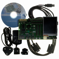
... Scope The AT91SAM9RL-EK evaluation kit enables the evaluation of and code development for applications running on an AT91SAM9RL device. It significantly reduces design cycle time, increasing confidence in a right-first-time system solution. This guide focuses on the AT91SAM9RL-EK board as an evaluation platform. The board supports the AT91SAM9RL in an LFBGA217 package. ...
Page 6
... MCI SD/MMC card slot four expansion connectors (PIOA, PIOB, PIOC, PIOD) one BGA-like EBI expansion footprint connector one Lithium Coin Cell Battery Retainer for 12 mm cell size 1-2 6325C–ATARM–22-Jul-10 AT91SAM9RL-EK Evaluation Board User Guide ...
Page 7
... Electrostatic Warning Upon delivery, the AT91SAM9RL-EK evaluation board is wrapped in a protective anti-static bag. The board must not be exposed to electrostatic discharges. A grounding strap or similar protective device should be worn when handling the board. Avoid touching the component pins or any other on-board metallic element. ...
Page 8
... Setting Up the AT91SAM9RL-EK Board 2.3 Layout Figure 2-1. AT91SAM9RL-EK Layout - Top View 2-2 6325C–ATARM–22-Jul-10 AT91SAM9RL-EK Evaluation Board User Guide ...
Page 9
... Figure 2-2. AT91SAM9RL-EK Layout - Bottom View AT91SAM9RL-EK Evaluation Board User Guide Setting Up the AT91SAM9RL-EK Board 6325C–ATARM–22-Jul-10 2-3 ...
Page 10
... Setting Up the AT91SAM9RL-EK Board 2.4 Powering Up the Board The AT91SAM9RL-EK requires 5V DC (±5%). DC power is supplied to the board via the 2 5.5 mm socket J1. Coaxial plug center positive standard. 2.5 Backup Power Supply The user has the possibility to plug a battery (3V Lithium Battery CR1225 or equivalent) in order to per- manently power the backup part of the device ...
Page 11
... AT91SAM9RL-EK Block Diagram Figure 2-3. AT91SAM9RL-EK Block Diagram SDRAM NANFLASH INTERFACE 12VDC OUT IN MIC USER'S AT91SAM9RL-EK Evaluation Board User Guide DATAFLASH EEPROM SD/SDIO MMC SERIAL SERIAL RS232 INTERFACE LCD USB Setting Up the AT91SAM9RL-EK Board 6325C–ATARM–22-Jul-10 2-5 ...
Page 12
... High Speed (480 Mbit/s) USB 2.0 Device Controller – On-Chip High Speed Transceiver, UTMI+ Physical Interface – Integrated FIFOs and Dedicated DMA – 4 Kbyte Configurable Integrated DPRAM Fully-featured System Controller, including – Reset Controller, Shutdown Controller AT91SAM9RL-EK Evaluation Board User Guide ™ ® ® ARM Thumb Processor ® ...
Page 13
... Input Change Interrupt Capability on Each I/O Line – Individually Programmable Open-drain, Pull-up resistor and Synchronous Output 24-channel Peripheral DMA Controller (PDC) One Multimedia Card Interface (MCI) – SDCard/SDIO 1.0 and MultiMedia Card 3.1 Compliant 3-2 6325C–ATARM–22-Jul-10 AT91SAM9RL-EK Evaluation Board User Guide ...
Page 14
... VDDCORE, VDDPLLB and VDDBU – 3.0V to 3.6V for VDDPLLA, VDDANA, VDDUTMI and VDDIOP – Programmable 1.65V to 1.95V or 3.0V to 3.6V for VDDIOM Available in a 144-ball BGA (AT91SAM9R64) and a 217-ball LFBGA (AT91SAM9RL64) Package AT91SAM9RL-EK Evaluation Board User Guide Board Description 3-3 6325C–ATARM–22-Jul-10 ...
Page 15
... DMA SDRAM Controller 2-channel DMA Static Memory Controller PDC Touch PDC Screen Controller SSC0 SSC1 6-channel 10-bit ADC AT91SAM9RL-EK Evaluation Board User Guide D0-D15 A0/NBS0 A1/NBS2/NWR2 A2-A15 A16/BA0 A17/BA1 NCS0 NCS1/SDCS NRD/CFOE NWR0/NWE/CFWE NWR1/NBS1/CFIOR NWR3/NBS3/CFIOW SDCK, SDCKE RAS, CAS SDWE, SDA10 ...
Page 16
... One Mono/Stereo Microphone input. 3.11 User Interface Two user input pushbuttons Two user green LED One yellow power LED (can be also software controlled) 3.12 Debug Interface 20-pin JTAG/ICE interface connector DBGU COM port AT91SAM9RL-EK Evaluation Board User Guide Board Description 3-5 6325C–ATARM–22-Jul-10 ...
Page 17
... Atmel application note no. 6309. This allows the developer to check the integrity of the components and to extend the features of the board by adding external hardware components or boards. 3-6 6325C–ATARM–22-Jul-10 Connecting EBI Memory Daughter Boards to AT91SAM Evaluation Boards, lit. AT91SAM9RL-EK Evaluation Board User Guide ...
Page 18
... MOSI PA27 SPCK PA28 NPCS0 PA29 RTS2 PA30 CTS2 PA31 NWAIT AT91SAM9RL-EK Evaluation Board User Guide SD/MMC CARD READER SD/MMC CARD READER SD/MMC CARD READER TCLK0 SD/MMC CARD READER TIOA0 SD/MMC CARD READER TIOB0 SD/MMC CARD READER RS232 COM PORT RS232 COM PORT ...
Page 19
... NANDWE NCS3/NANDCS D16 D17 D18 D19 D20 D21 D22 D23 D24 D25 D26 D27 D28 D29 D30 D31 AT91SAM9RL-EK Evaluation Board User Guide Powered by VDDIOP VDDIOP VDDIOM VDDIOM VDDIOM VDDIOM VDDIOM VDDIOM VDDIOM VDDIOM VDDIOM VDDIOM VDDIOM VDDIOM VDDIOM VDDIOM VDDIOM ...
Page 20
... LCDD23 PC26 LCDD18 PC27 LCDD19 PC28 LCDD20 PC29 LCDD21 PC30 LCDD22 PC31 LCDD23 AT91SAM9RL-EK Evaluation Board User Guide LCD PANEL PWM0 PWM1 LCD PANEL LCD PANEL LCD PANEL LCD PANEL LCD PANEL LCD PANEL LCD PANEL LCD PANEL LCD PANEL LCD PANEL ...
Page 21
... PWM1 USER LED 1 PWM2 USER LED 2 NAND FLASH MEMORY Application Usage AC97_FS AC97_CK AC97_TX AC97_RX PD14 or PWM0 PD15 or PWM1 PD16 or PWM2 PD17 as RDYBSY AT91SAM9RL-EK Evaluation Board User Guide Powered by VDDIOP VDDIOP VDDIOP VDDIOP VDDIOP VDDIOP VDDIOP VDDIOP VDDIOP VDDIOP VDDIOP VDDIOP ...
Page 22
... JTAG/ICE Table 4-2. JTAG/ICE Configuration Designation S1 R11 R13 AT91SAM9RL-EK Evaluation Board User Guide Default Setting (1) Closed 3.3V Jumper Forces power on. Closed To use the software shutdown control, J3 must be opened. 3V battery backup must be present ...
Page 23
... Enables the use of the DATAFLASH device Opened Disables the write protect. Default Setting Soldered USB DEVICE: Enables the use of the USBCNX signal Soldered Enables the use of DTXD output signal Soldered Enables the use of DRXD input Feature Feature Feature AT91SAM9RL-EK Evaluation Board User Guide ...
Page 24
... Table 4-5. Miscellaneous Designation R70 R71 R72 R73 TP1 TP2 TP3 AT91SAM9RL-EK Evaluation Board User Guide Default Setting Soldered TXD Soldered RTS Soldered RXD Soldered CTS N.A GND Test point N.A GND Test point N.A GND Test point Feature 6325C–ATARM–22-Jul-10 ...
Page 25
... Board Schematics This section contains the following schematics: Board Diagram - Schematic Top Level Power supply AT91SAM9RL Microcontroller EBI Memory Serial Memory Audio AC97 Serial Interface TFT LCD display Expansion connectors AT91SAM9RL-EK Evaluation Board User Guide Section 5 Schematics 5-1 6325C–ATARM–22-Jul-10 ...
Page 26
...
Page 27
...
Page 28
...
Page 29
...
Page 30
...
Page 31
...
Page 32
...
Page 33
...
Page 34
...
Page 35
... VDDCORE Power Consumption Measurement Impossible If the AT91SAM9RL64 device is an engineering sample (ES), VDDCORE power consumption measure- ment is impossible on J10 Jumper. Problem Fix/Workaround None. AT91SAM9RL-EK Evaluation Board User Guide Section 6 Errata 6-1 6325C–ATARM–22-Jul-10 ...
Page 36
... Impossible” CFE1 and CFE2 changed into CFCE1 and CFCE2 in 6325B Section 6.1 ”Pull-up Resistor on the Wrong Pin” 6325A First issue. AT91SAM9RL-EK Evaluation Board User Guide errata added Section 7 Revision History Change Request Ref. 7188 Table 3-2 on page 3-8 ...
Page 37
... Revision History 7-2 6325C–ATARM–22-Jul-10 AT91SAM9RL-EK Evaluation Board User Guide ...
Page 38
... Disclaimer: The information in this document is provided in connection with Atmel products. No license, express or implied, by estoppel or otherwise, to any intellectual property right is granted by this document or in connection with the sale of Atmel products. EXCEPT AS SET FORTH IN ATMEL’S TERMS AND CONDI- TIONS OF SALE LOCATED ON ATMEL’S WEB SITE, ATMEL ASSUMES NO LIABILITY WHATSOEVER AND DISCLAIMS ANY EXPRESS, IMPLIED OR STATUTORY WARRANTY RELATING TO ITS PRODUCTS INCLUDING, BUT NOT LIMITED TO, THE IMPLIED WARRANTY OF MERCHANTABILITY, FITNESS FOR A PARTICULAR PURPOSE, OR NON-INFRINGEMENT ...