CT-161-CD Fujitsu Semiconductor America Inc, CT-161-CD Datasheet
CT-161-CD
Specifications of CT-161-CD
Available stocks


Related parts for CT-161-CD


CT-161-CD Summary of contents
Page 1
... FUJITSU Electronic Devices User's Manual 2 F MC-16LX STARTER KIT USER'S MANUAL ...
Page 2
Revision History Date Jun 27, 2005 Edition 1.0: Initial release Description © Fujitsu ...
Page 3
... Fujitsu will not assume responsibility for infringement of any intellectual property or other rights of third parties arising from the use of the information or circuit diagrams any products described in this document represent goods or technologies subject to certain ...
Page 4
... Installing of integrated development environment "SOFTUNE" (limited-function version) ................................................................................... 10 1.1.3 Installing of demonstration version (trial version) of ACCEMIC MDE ................ 16 1.1.4 Setting up of evaluation board and connecting of board to the personal computer.............................................................................................................. 21 1.1.5 Starting and setting up of SOFTUNE ..................................................................... 23 1.1.6 Starting and setting up of ACCEMIC MDE ........................................................... 26 1.1.7 Terminating of ACCEMIC MDE ...
Page 5
... Changing the tone of a buzzer sound...................................................................... 62 5 “Let's try to control the LED by interrupt.” ............................................................... 63 5.1 What is an interrupt? .................................................................................................. 63 5.2 How to detect a switch operation by interrupts.......................................................... 64 5.3 How to create and execute a program to control the LED by switch Input operation ................................................................................................................. 65 5.3.1 Outline of the program to be created ...................................................................... 65 5 ...
Page 6
How to create and execute a program to display temperature ................................... 85 8.3.1 Outline of the program to be created ...................................................................... 85 8.3.2 Creation and execution of the program................................................................... 88 A Appendix (Program Creation Procedure)................................................................... 90 A.1 Program Creation ...
Page 7
... Therefore, this User's Manual has been written specifically for questions that beginners of microcomputers usually have. The Starter Kit can be effectively used as a tool for training about electronic circuits or as introductory education for embedded-software developers in classes at universities, technical colleges, and industrial high schools, as well as in new-employee education programs at corporations ...
Page 8
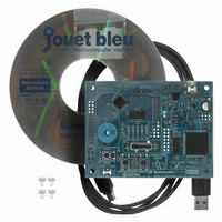
... Before setting up the Starter Kit, make sure that all the components and equipment listed in Table 1.1 are ready for use. You should install the software on your personal computer before connecting the evaluation board to the personal computer. The Starter Kit software is available in two versions: A CD-ROM version and a download version (the download version is not delivered on CD-ROM) ...
Page 9
... Target device expansion pin (CN1) (1)Target device (9)Buzzer (3)Reset switch (4)MODE switch © Fujitsu (2)Target device expansion pin(CN2) (13) Oscillator for (10) USB host connecter main microcomputer (5)LED (8)Temperature (6) Test switch sensor (7) A/D test VR Figure 1.1 Board (12) USB communication microcomputer expansion pin ...
Page 10
Figure 1 circuit diagram for the evaluation board. Figure 1.2 Evaluation board circuit diagram © Fujitsu ...
Page 11
... Kyocera's separate-excitation type piezo alarm with a case (KBS-13DB-4P- connected to the PPG timer output pin. A USB pin to connect the evaluation board and the host PC A USB communication microcomputer to connect the main microcomputer (MB90F387S) and the host PC It contains the USB communication firmware that has been developed by Interface Co ...
Page 12
... Prepare a personal computer by yourself. Figure 1.3 Connect the board to the personal computer by using the accessory USB cable. Supply power to the board by USB bus power system. Be sure to connect the USB cable directly to the personal computer. Do not connect the USB cable via a USB hub. System configuration 6 ...
Page 13
... Table 1.3 shows the assignment of functions to the pins of MB90F387 microcomputer. Table 1.3 Function assignments to the pins of F Pin-No. Function Connection destination 3 P50/AN0 VR 4 P51/AN1 TEMP.SENSOR 17 P25/INT5 SW1 19 P27/INT7 SW2 20 MD2 MODE 21 MD1 PULL-UP 22 MD0 MODE 23 RST RESET 29 P10/IN0 LED1 30 P11/IN1 LED2 ...
Page 14
... Setting Up of Personal Computer This section describes how to install the software required to operate the Starter Kit on the personal computer. (Be sure to perform the software installation operation before connecting the board to the personal computer.) Take the following steps to set up the personal computer: ① ...
Page 15
Installing of USB driver Install the USB driver according to the content of the "USB Driver Installation Manual". © Fujitsu ...
Page 16
... Install SOFTUNE (limited-function version). The limited-function version of SOFTUNE is subject to the limitation on the program size that can be debugged to 32 kilobytes. The limited-function version cannot be used to create a program over 32 kB. ① Insert the CD-ROM into the CD-ROM drive. When using the download version, download the software for F open the folder where the files are decompressed ...
Page 17
Fujitsu Click 'Next >.' Click 'Next >.' ...
Page 18
If you accept the agreement, click 'Yes.' (If you refuse the agreement, you cannot install SOFTUNE.) Click 'Next >.' © Fujitsu ...
Page 19
Fujitsu Click 'Next >.' Click 'Next >.' ...
Page 20
Click 'Next >.' The installation is executed © Fujitsu ...
Page 21
... The installation of SOFTUNE (limited-function version) is completed. Proceed to the installation of the demonstration version of ACCEMIC MDE. © Fujitsu Click 'Finish ...
Page 22
... Installing of demonstration version (trial version) of ACCEMIC MDE Install the demonstration version (trial version) of ACCEMIC MDE. The trial version of ACCEMIC MDE is subject to a limitation on the size of the program that can be debugged to 12 kB. The trial version cannot be used to create a program over 12 kB. ...
Page 23
ACCEMIC MDE.) © Fujitsu If you accept the agreement, click 'Yes.' Click 'Next >.' ...
Page 24
Click 'Next >.' (Do not change the installation-destination folder here.) Click 'Next >.' © Fujitsu ...
Page 25
Fujitsu Click 'Next >.' The installation is executed ...
Page 26
... When the installation is completed, click 'Finish >.' Installation of the demonstration version of ACCEMIC MDE is completed. Proceed to the setup of the evaluation board and its connection to the personal computer © Fujitsu ...
Page 27
... Setting up of evaluation board and connecting of board to the personal computer After the installation of SOFTUNE and ACCEMIC MDE, perform switch setting on the evaluation board and connect the board to the personal computer. On the evaluation board, set the MODE selector to PROG. MODE selector ...
Page 28
... Connect the USB port of the evaluation board to a USB port of the personal computer using the accessory USB cable. Do not connect the USB cable via a USB hub, but connect it directly between the board and personal computer. Connect the USB cable to a USB port of the personal computer. ...
Page 29
... Uncompress the Fujitsu_starter_kit.zip file included in the CD-ROM or among the downloaded files in an arbitrary directory. Start SOFTUNE (limited-function version). From the Start menu of Windows, select Programs (P) and Softune V3, in this order, and then click on FFMC-16 Family Softune Workbench (trial version) to start. Open the workspace file for sample programs. ...
Page 30
... In this step, the workspace file to execute a sample program is opened. (No sample program is executed when the workspace file is opened.) Open the Start_kit.wsp file located in the Fujitsu_starter_kit folder. The project window displays the opened workspace © Fujitsu ...
Page 31
... Since program debugging is performed in units of projects, you should specify the project to be debugged as an active project. Select a project to be debugged and click the right mouse button. A submenu appears. Select Set active project from the submenu. The project name in the list is displayed in boldface, and debugging of the project is enabled. © Fujitsu 25 - ...
Page 32
... Starting and setting up of ACCEMIC MDE Use the Start_kit.wsp workspace file opened in the previous step to start ACCEMIC MDE. Confirm that the current active project of SOFTUNE is special.prj. Select Build (B) from the Project (P) menu to execute a build operation. When the build operation is executed, the output screen of SOFTUNE displays the messages below ...
Page 33
... If an error is detected as shown below in the build operation, perform the software installation again from the initial step as described in Item 1.1.2. reinstalling the software, displayed on the Build operation started... -------------------- Configuration: special.prj - Debug-------------------- start905s.asm monitor16LX.asm _FFMC16.C *** D:¥jouet_bleu¥Fujitsu_start_kit¥special¥_ffmc16.c(9) E4038P: #include: File "_ffmc16.h" is not found. … ...
Page 34
... Subsequently, ACCEMIC MDE starts automatically. Input the COM port number that is confirmed after the USB driver is installed. If you need to correct settings in the 'Select Processor dialog box' because you made an incorrect "Type" setting or for other reasons, select 'Communication...' from the Preferences menu to display the 'Select Processor dialog box.' If the COM port number is unknown, use the following procedure to check the COM port number to which the board is connected ...
Page 35
When the Property window of the system appears, click "Hardware," and then click "Device manager (D)." When the Device manager window appears, check the indication of "INTERFACE USB to RS232C Converter Virtual COM Port(COMx)" under the "Port (COM and LPT." ...
Page 36
... Click 'OK.' (With this trial version, the OK input will take effect 10 seconds later.) Make the settings of the target microcomputer. When you use ACCEMIC MDE for the first time, you should download the monitor debugger kernel. (You need not make these settings again unless you change the target microcomputer.) Here, select Fujitsu for " ...
Page 37
... When you click OK after pressing the 'RESET' switch on the board, downloading starts. If the above switch operation is not performed in correct order, ACCEMIC MDE will not start. If you fail to perform switch operation correctly, resume the operation from the step described in Item 1.1.6. © Fujitsu ...
Page 38
... When downloading ends, the next information item appears. Information dialog box displayed, necessary switch operations on the board Reconfirm that the selector is set to the "PROG" side. Press the 'RESET' switch. With the next do not click OK immediately but perform MODE When this dialog box is displayed, do not click OK immediately, but ...
Page 39
... When you click 'OK' in the Information dialog box after pressing the 'RESET' switch on the board, ACCEMIC MDE starts. © Fujitsu Set the MODE selector to RUN. Press the 'RESET' switch Now, click 'OK.' ...
Page 40
... The ACCEMIC MDE window opens. Execute the program of the sample project "special.prj." Select "Run" under "Start." The LEDs the board are shifted leftward respectively at one-second interval. It also has the functions listed in Table 1- When the program is executed, the LEDs the ...
Page 41
... SW2 normal press SW1 long press Volume adjustment © Fujitsu Board operation The LED shift direction is changed. Shift direction: Left shift Right shift - - - - The shift speed is changed. Shift speed: 1 second 0.5 seconds seconds 1 seconds controls on and off of the buzzer. ...
Page 42
... Stop the program as follows: Select Stop from the Start menu to stop the sample program. Reset the program as follows: Select Restart from the Start menu. The program is reset © Fujitsu ...
Page 43
... Terminating of ACCEMIC MDE To terminate ACCEMIC MDE, select 'Exit' from the File menu. The ACCEMIC MDE window closes. 1.1.8 Terminating of SOFTUNE After terminating ACCEMIC MDE, terminate SOFTUNE as follows: Select 'Exit' from the File menu to terminate SOFTUNE. The SOFTUNE window closes. Described above are the basic operation procedures using sample programs to start debugging. © ...
Page 44
... Item 1.1.6. Confirm that the program runs on ACCEMIC MDE normally. Then, stop the program, and select "Automatic Start" under "Tools" in the menu. Then, the following window appears. Then, put a checkmark on "Automatic start after reset," and press "OK." ...
Page 45
... After the writing ends, stop ACCEMIC MDE and SFTUNE. Then, press the "RESET" button on the board while the USB cable is connected. The same operations as confirmed on ACCEMIC MDE are available. Described above are the basic operation procedures by using the sample programs to start debugging. ...
Page 46
... An LED has two electrodes: anode and cathode. When a voltage is applied across the LED so that the anode positive potential with respect to the cathode, a current flows and the LED emits light. In the circuit shown in Figure 2.1, the LED goes on (emits light) when the switch (SW) is turned on and goes off when the switch is turned off ...
Page 47
... When an electron hole and an electron are combined together, they lose their energy partially, and the lost energy is emitted in the form of light. The color of emitted light depends on the material of the semiconductor. Table 2.1 shows examples of semiconductor materials and corresponding colors of emitted light. ...
Page 48
... This section explains how to control the switch using a microcomputer.Figure 2.4shows the connection of LEDs to the microcomputer on the board. Figure 2.5 shows a conceptual diagram of the connection. In the case of (a) in Figure 2.5, the signal output from pin P10 is at the high level. Therefore, no current flows through the LED and the LED is off ...
Page 49
... Registers are the memory areas to control microcomputer operation and retain microcomputer operation status. Writing data to, and reading data from registers enables you to control the CPU and peripheral functions of the microcomputer. Here, the term peripheral functions means the functions of the I-O ports, timers, and A/D converter incorporated in the microcomputer. bit ...
Page 50
... LED on/off control by rewriting the PDR1 register (with a conceptual diagram of the Figure 2.7 On the board, the LEDs are connected to pins P10 to P14. Therefore, the five pins are set to the output mode for controlling the LEDs. When the microcomputer is reset, all bits of DDR are reset to 0 (initial value), which means the ports are set to the input mode ...
Page 51
... After the input of the program, build the program according to the procedure described in Appendix A. error message is output, check that the content of the input program is exactly the same as the description shown in Figure 2.9. When the build operation ends successfully, ACCEMIC MDE starts automatically. ...
Page 52
... Appendix B.1. 2.5 How to create and execute a program to make the LED blinking This section explains how to create a program that makes the LED be blinking. 2.5.1 Outline of the program to be created Here, you will create a program that switches the output from pin P14 of the microcomputer between the low and high levels repeatedly to make LED5 turn on and off repeatedly ...
Page 53
... After the input of the program, build the program according to the procedure described in Appendix A. error message is output, check that the content of the input program is exactly the same as the description shown in Figure 2.11. When the build operation ends successfully, ACCEMIC MDE starts automatically. ...
Page 54
IO_PDR1.byte=0xEF; IO_DDR1.byte=0x1F; while(1) { int i; for(i=0;i<30000;i++); IO_PDR1.byte=0xFF; for(i=0;i<30000;i++); IO_PDR1.byte=0xEF; } Program to be added } Figure 2.11 Program to make LED5 blinking (1) LED5 on setting (P14=Low, P10 to P13 =High) (2) P10 to P14 output ...
Page 55
... P25 becomes GND. Thus, the input status at pin P25 of the microcomputer changes depending on the state of SW1. The same mechanism applies to SW2, except that SW2 is connected to pin P27, which is a general I-O port of the microcomputer. Therefore, the input status at pin P27 changes when SW2 is operated. ...
Page 56
... The change of pin status can be detected by a program running on the microcomputer The microcomputer of the Starter Kit can determine the status of pins P25 and P27 from the corresponding values in an I-O port register (PDR2). Register values can be read using instructions of a microcomputer program. In other words, the microcomputer can determine the operation state of a switch by reading the corresponding value from PDR2 by the program ...
Page 57
... How to create and execute a program to control LEDs by switch operation This section explains how to create a program to detect the switch operation state. The program also controls LED operation to enable you to visually know that the switch operation state is detected. The program applies the method of turning on the LED described in the previous chapter. 3.2.1 Outline of program to be created The operation of the program to be created is as described below ...
Page 58
... PDR2 to detect the state of SW1. The program turns on or off LED1 according to the read value. To turn on and off LED1, the program writes respectively, to the bit 0 of PDR1. Also for SW2, the program performs the similar processing and controls LED2. ...
Page 59
Descriptions ”IO_XXX.byte” and ”IO_YYY.bit” included in the above program code are the convenient formats of description defined in the I-O header file. information, see Appendix B.1. © Fujitsu For further ...
Page 60
... Before explaining the mechanism of a buzzer, this section describes the piezoelectric device that is used for a buzzer. A piezoelectric device is a circuit element that uses a piezoelectric effect. The piezoelectric device incorporates a substance characterized by the piezoelectric effect (which causes a voltage when an impact or pressure is applied) or the inverse piezoelectric effect (which causes a crystalline distortion when a voltage is applied) ...
Page 61
... Figure 4.1 Polarization of molecules and crystal 4.1.2 Piezoelectric characteristics As shown in Figure 4.2, a crystal sometimes has a characteristic that expands the crystal when a voltage is applied in the direction of polarization (direction of green arrow). This characteristic is called the piezoelectric effect. When a piezoelectric crystal is given a voltage in the reverse direction of polarization (reverse direction of green arrow), the crystal contracts ...
Page 62
... Microcomputer and piezoelectric buzzer A piezoelectric buzzer uses a piezoelectric device as described above. To produce a sound from the piezoelectric buzzer, you should apply a changing voltage, e.g pulse voltage, to the buzzer. Here, let's sound a piezoelectric buzzer by using a pulse wave (pulse voltage) output from the microcomputer. Vibration Figure 4 ...
Page 63
Self-excited and separately excited vibrations Buzzers are classified into two types. One type, called a self-excited buzzer, generates only one sound by the self-resonance of the crystal when a voltage is applied. The other type, called a separately excited ...
Page 64
... When the PPG count clock is set, the cycle of pulse set in Item 4.3.1 is determined. 4.4 How to create and execute a program to sound the buzzer Here, let's create a program to actually control the operation of the PPG timer in the microcomputer and sound the buzzer. H-level duration ...
Page 65
... PPG setting in the microcomputer. Writing a value to a register is a programmed operation in by which the value is set in the register according to an instruction. Here, try to make settings for the output kHz pulse wave as an example. To make the setting easier, specify an equal count for L-level and H-level duration, and specify the PPG count clock same as the internal CPU operating frequency ...
Page 66
... After the input of the program, build the program according to the procedure described in Appendix A. error message is output, check that the content of the input program is exactly the same as the description shown in the figure below. When the build operation ends successfully, ACCEMIC MDE starts automatically ...
Page 67
Table 4.2 Correspondence of counts and pulse frequencies (with operating frequency at 2 MHz) Count per cycle (L-level duration + H-level duration) After the PPG pulse output is started by the program and the buzzer starts sounding, the buzzer sound ...
Page 68
Changing the tone of a buzzer sound Try to vary the setting of pulse duration to check how the buzzer sound changes. Our audible frequencies are said to range from kHz. Try to confirm the ...
Page 69
... LED by interrupt.” A method to detect the switch operation state was described in Chapter 3. There are also other methods to detect switch operation than the one described in Chapter 3. One of the other methods is to use an external interrupt input. operation by using an external interrupt input. ...
Page 70
... How to detect a switch operation by interrupts As described in Chapter 3, the board of the Starter Kit has two switches that are connected to pins P25 and P27 of the microcomputer. Pins P25 and P27 connecting the switches were used as input ports in the program example described in Chapter 3. These pins can be used also as external interrupt input pins (INT5 and INT7) ...
Page 71
... Explained next is the procedure for using pin INT5 as an external interrupt pin. To use pin INT5 for the input of external interrupt, you should set the I-O direction of the pin to input by using the port 2 register "DDR2." Handling of DDR2 was described in Chapter 3. Write '0' to the bit 5 of DDR2. You should also set necessary values in external interrupt registers " ...
Page 72
... ACCEMIC screen. When SW1 is pressed after the external interrupt is enabled, an INT5 interrupt is generated, and an interrupt routine is called. The interrupt routine clears the interrupt factor and switches LED3 between on and off states. In summary, this program makes LED1 blinking processing usually as the main processing, and switches LED3 between the on and off states only when the interrupt is generated by switch operation ...
Page 73
... Appendix A. error message is output, check that the content of the input program is correct. When the build operation ends successfully, ACCEMIC MDE starts automatically. After the ACCEMIC MDE window appears, execute the program and check its operation. ...
Page 74
... The ext_int function is called when the external interrupt (INT5) is generated. If you program the above operation without using this sample project, you should register the interrupt routine in the vector table so that the ext_int function will be called when the external interrupt (INT5) is generated. You need not perform the registration when you use this sample project in which the interrupt routine has already been registered. Descriptions ” ...
Page 75
... People can re-realize that the timer function of the alarm clock allows us to sleep tight until the time to get up. The microcomputer has the timer interrupt function that performs as an alarm timer function. ...
Page 76
... Outline of the program to be created In Chapter 2, the LED blinking time is controlled by a WAIT of the loop processing. In this section, a program that uses the 16-bit reload timer interrupt to count the LED blinking time is created. The LED operation of this program is the same as that of the program created in Chapter 2 ...
Page 77
... Software start factor of timer (starts operation) Infinite loop The program created in this section goes into an infinite loop (No the flow of the program) after a sequence of the processing. During this infinite loop processing, the CPU can execute any processing other then the LED processing. Table 6-1 Register setting of 16-bit reload timer shows the register of the 16-bit reload timer that is set in the program created in this section ...
Page 78
... When the "ACCEMIC MDE" window appears, execute the program and check the operation. For the procedure of the program execution, see Appendix A.3. When the program starts correctly, check LED5. Blinking LED5 indicates the normal operation. Setting value (meaning) 0 × F424 (62500 counts) ...
Page 79
... The reload_int function in Figure 6-5 Example of program code (interrupt routine executed when an interrupt of the 16-bit reload timer is generated normally required to register the interrupt routine on the vector table so that the reload_int function is executed when an interrupt of the 16-bit reload timer is generated. In this sample project, however, it has already been registered can be used without registration. In the above code, there are some expressions such as " ...
Page 80
... A/D converter.” This section describes the processing to convert the analog signals input to the microcomputer into the digital signals by using the A/D converter and to load the digital signals into the microcomputer. This Starter Kit can control the value of the voltage applied to the analog pin for the A/D converter by using the volume tab mounted on the board ...
Page 81
... A digital value is a value into which an analog value is divided according to a standard based on a certain rule. The A/D converter is mounted on the microcomputer to perform this conversion. For this conversion, the important factor is resolution. This resolution is, like the resolution of photograph, a scale of how small the analog value resolved and converted to the digital value ...
Page 82
... Outline of program to be created Let us now create the actual program. The contents of the program are to use the A/D converter to digitalize the potential of the applied voltage and to determine the number of LEDs to be lighted according to the potential. The main operation of the program is described below ...
Page 83
... A/D conversion, operation mode, and A/D input channels. In this section, the sampling time is set to 128/ φ , the comparing time is set to 176/ φ , the resolution is set to 8-bit 、 and the A/D conversion channel to be used is set to Ch0 only, and the operation mode is set to the continuous conversion mode. " ...
Page 84
... The operation repeats as shown above. When the A/D conversion ends, an interrupt of the A/D converter is generated, and an interrupt routine is called. In the interrupt routine, the interrupt factor is cleared, the A/D value is obtained, and the LEDs are lighted according to the obtained A/D value, which is the volume size. The correspondence between the volume size and the number of LEDs lighted is as shown in Table 7 ...
Page 85
... A/D converter interrupt permission (ADCS:H.byte13 = 1) A/D conversion started (ADCS:H.byte9 = 1) Infinite loop © Fujitsu Interrupt occurs by A/D conversion end External interrupt processing starts. (1) External interrupt factor is cleared. (ADCS:H.bit14 = 0) (2) Turns on/off LED3. (PDR1.bit2 = !(PDR1.bit2)) (3) Obtain A/D value. (AD_DATA = ADCR:L.byte) AD_DATA<42 N (4) AD_DATA< ...
Page 86
... When the “ ACCEMIC MDE ” window appears, execute the program and check the operation. For the procedure of the program execution, see Appendix A.3. When the program starts correctly, check the operation. It can be confirmed that the LEDs are lighted according to the size of the applied voltage that has been adjusted on the volume ...
Page 87
... It is generally required to register the interrupt routine on the vector table so that the ADC_int function is executed when an interrupt of the A/D converter is generated. In this sample project, however, it has already been registered can be used without the registration. In the above code, there are some expressions such as "IO_XXX.byte" or "IO_YYY.bit." ...
Page 88
... There are various sensors for different purposes and requirements, and one of those various sensors is the temperature sensor. The temperature sensor is, as its name suggests, a sensor to detect changes in temperature. Examples of what the temperature sensor is used for include the temperature control features of air conditioners and refrigerators. In this way, various sensor s are used for household appliances ...
Page 89
... To use the temperature sensor and detect temperature necessary to understand the specifications of the sensor. The specifications of the sensor to be used (NTCG164BH103 ) can be confirmed on the sensor data sheet, which is issued from the manufacturer. The data sheet of the temperature sensor contains the information required for measurement. For this time, the relationship between the measured temperature and the state of the sensor (resistance value) is especially important ...
Page 90
Figure 8-2 Peripheral circuit diagram of "temperature sensor" (image) shows the peripheral circuit diagram of the "temperature sensor" on the Starter Kit board. In this circuit, when the resistance of the "temperature sensor" changes, the input voltage of the A/D ...
Page 91
... Outline of the program to be created Let us now create the actual program. The contents of the program are to use the A/D converter to obtain the temperature information of the sensor, and to control the lighting of the LED (to change the lighting pattern) according to the obtained value. For processing related to the A/D converter, create the program based on the program of the volume control A/D converter that is created in the previous chapter ...
Page 92
... When the A/D conversion ends, an interrupt of the A/D converter is generated, and an interrupt routine is called. In the interrupt routine, the interrupt factor is cleared, the A/D value is obtained, and the LEDs are lighted according to the obtained A/D value. The LED lighting processing is as shown in Table 8.4 LED lighting processing. ...
Page 93
... A/D converter interrupt permission (ADCS:H.byte13 = 1) A/D conversion started (ADCS:H.byte9 = 1) Infinite loop © Fujitsu Interrupt occurs by A/D conversion end External interrupt processing starts (1) External interrupt factor is cleared (ADCS:H.bit14 = 0) (2) Turns on/off LED3 (PDR1.bit2 = !(PDR1.bit2)) (3) Obtain A/D converted value. (AD_DATA = ADCR:L.byte) AD_DATA>171 N (4) AD_DATA> ...
Page 94
... LEDs. When the temperature of the room where the operation is performed is between 10 and 20 The number of LEDs lighted varies with the temperature detected by the sensor. For example, warm up the sensor part using your fingers. When warming up the peripheral part of the sensor, be aware of the temperature ...
Page 95
... The ADC_int function executed when an interrupt of the A/D converter is generated normally required to register the interrupt routine on the vector table so that the ADC_int function is executed when an interrupt of the A/D converter is generated. In this sample project, however, it has already been registered can be used without registration. In the above code, there are expressions such as " ...
Page 96
... This appendix explains the procedure you should follow when creating an actual program. First, start up SOFTUNE as instructed in Item 1.1.5, "Starting and setting up of SOFTUNE," (pages 15 to 17), and open the Start_kit.wsp file. Use the sample project provided for easy creation of software. To use the sample project, select "Sample.prj" in the list, right-click to open a submenu, and select 'Set active project' from the submenu. Then, the string including " ...
Page 97
... Click on "Sample.prj" to show the list of folders below. Click on "main.c" under the Source Files folder to open the main.c file. After the main.c file is opened, create your program in the section indicated by the red dotted line below. #include "_ffmc16.h" #include "extern.h" //#include "monitor.h" void main(void) ...
Page 98
... While editing a source file, select 'Save As...(A)' from the File menu. The dialog box below appears. Select Text file, and then click 'OK.' Next, the dialog box below appears. Select the folder to save the program in the Save in field, specify the file name in the File name field, and then click 'Save.' ...
Page 99
The saved file is still displayed. Close the displayed file. After closing the saved file, find the original file name of the saved file ("main_old.c in this example) in the Source Files folder under "Sample.prj" in the list, and then ...
Page 100
... A.2 Program Building Procedure After creating a program, confirm that the board is connected to the personal computer by the USB cable, and then start the procedure to build the program error is found in the created program, ACCEMIC MDE starts automatically and displays the information shown below for 10 s. This information is displayed only by the trial version of ACCEMIC MDE (not displayed by the product version) ...
Page 101
... If an error is found in the created program, the error is indicated as shown below. Correct the indicated error, and perform 'building' again. Error indication window © Fujitsu Click the error code to jump to the line that includes the error ...
Page 102
... A.3 Program Execution Method Execute the created program and check that it performs the intended operation. ACCEMIC MDE has started, the window as shown below appears: Use the buttons shown below to control the program. Function Button Continuous execution Stop Reset Operation (when clicked) Starts and runs the program continuously ...
Page 103
... An actual C-language program contains the descriptions of instructions to write values to various registers to specify microcomputer operation. The above description formats enable you to write values to registers in C language. For example, assume the instruction to write 0xff to the port 1 data register (PDR1), which is allocated at address 0x000001. The instruction is described in C language as follows: *((volatile char *)0x000001) = 0xFF ...
Page 104
... Select "Project setting(J)" under "Project(P)." Change the include path settings of the C compiler and the assembler as shown below. The following window shows the include path setting of the C compiler. Select this tab for setting the include path of the C. Delete the specified include path ...
Page 105
... Fujitsu Click this button to select a arbitrary directory. Select a folder Click the Add button to add the selected include path. After setting, click the OK button. ...
Page 106
... Use the same procedure for setting the include path of the assembler. Select this tab for setting the include path of the assembler. 100 - - © Fujitsu ...