MB2146-410A-01-E Fujitsu Semiconductor America Inc, MB2146-410A-01-E Datasheet
MB2146-410A-01-E
Specifications of MB2146-410A-01-E
Available stocks


Related parts for MB2146-410A-01-E


MB2146-410A-01-E Summary of contents
Page 1
... FUJITSU MICROELECTRONICS SUPPORT SYSTEM 2 F MC-8FX Family 8-bit MICROCONTROLLER MB95200H/210H Series STARTER KIT MB2146-410A-01-E SS01-26033-1E SETUP GUIDE ...
Page 2
... All information included in this document is current as of the date it is issued. Such information is subject to change without any prior notice. Please confirm the latest relevant information with the sales representatives. 2 MC* 1 -8FX Family Starter Kit: MB2146-410A-01-E* 2 MC-8FX MB95200H/210H series, which comes with MB2146-08 MB2146-410A ...
Page 3
Caution of the products described in this document The following precautions apply to the product described in this manual. Indicates a potentially hazardous situation which could result in death or serious WARNING injury and/or a fault in the user’s ...
Page 4
The contents of this document are subject to change without notice. Customers are advised to consult with sales representatives before ordering. • The information, such as descriptions of function and application circuit examples, in this document are presented sole- ...
Page 5
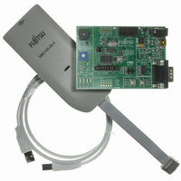
... Product Overview This product is a set of Starter Kit (MB2146-410A-01-E) of MB95200H/210H series composed of a BGMA (MB2146-08-E) and an EV-board (MB2146-410A-E). Combining the S Workbench on PC, the Starter kit enables the quick start of OFTUNE development before the user system is ready. 1.1 Objective and Deliverable The Starter kit (MB2146-410A-01-E) provides users a complete development platform. Before start using the Starter Kit, make sure that the following devices are placed in the package: • ...
Page 6
Feature The MB95200H/210H Series starter kit is the best for a performance and functional evaluation, and a check of operation before including MB95200H/210H Series in a user's system. Below, the feature of the BGM debugger for MB95200 Series is ...
Page 7
... This chapter gives introduction how to setup BGMA. 2.1 BGMA Overview Below is the close look of the BGMA. The Part Number of the MB95200 Series BGMA is MB2146- 08-E. It provides a debug platform for the MB95200 Series MCU in a small size (55.7mm (W) × 127mm (D) × 30mm (H)). ...
Page 8
IDC10 Interface Description Pin Number 2.4 BGMA USB Configuration The BGMA is provided with a USB cable. Connect the BGMA with a USB cable. If the ...
Page 9
Select “Install from a list or specific location (Advanced)”, then click “Next”, Figure 2.4-2 Install BGMA in Windows (2) Select “…\Drivers” from the folder where SOFTUNE is installed, click “Next”, Figure 2.4-3 Install BGMA in Windows (3) 5 ...
Page 10
... Select BGMA (MB2146-08) as displayed below, and then click “Next”, Windows will install the driver automatically. Click “Finish” after the driver has completed the installation normally. Then users can find the BGMA is recognized as MB2146-08 in Windows system. 6 Figure 2.4-4 Install BGMA in Windows (4) ...
Page 11
LED Description First, only plug USB cable to PC, check the Power LED on BGMA turns Green. Refer to Figure 2.5- 1. Second, plug IDC10 cable to the EV-board (target MCU board), then turn on EV-board. After that check ...
Page 12
EV-board Manual This chapter gives introduction how to setup EV-board. 3.1 EV-board Overview MB95200H/210H MCU EV-board is provided as a user-friendly introductory and evaluation plat- form for the MB95200H/210H MCU Family microcontroller. Figure 3.1-1 below is a close look ...
Page 13
... The EV-board consists of a board and a sample firmware. The board provides a useful platform for using the MCU and its peripherals useful development platform together with a BGMA (PN: MB2146-08-E) and a S • Clock and sub-clock • USB 5V power IF, external 5V power IF and the battery • ...
Page 14
EV-board Schematic 10 Figure 3.3-1 EV-board Schematic ...
Page 15
HW Module Description and Jumper settings 3.4.1 Power Module EV-board has 4 kinds of power supply for user to choose. Please read below instructions before us- ing. • DC Adaptor: 9V DC: Output voltage: 9V Connection: Connector (CN6) • ...
Page 16
The following two power supplies are recommended. Please follow the settings below, Power supply 4 AA batteries from BT1 on the back of the EV- board from CN6 Please do not connect several power supplies at the same ...
Page 17
Clock Settings The MB95200H/210H series MCU uses an internal main clock source by default. Users can select on-board crystal as a main clock and a sub-clock. Follow the settings below: Clock Header name Main clock SW3: ...
Page 18
LED Module There are four LEDs on EV-board to demonstrate the I/O function. Enable LED2, LED3 and LED4 in the following table, Modules LED*: LED2, LED3, LED4 * : LED module has four LEDs in total, but P12 (LED1) ...
Page 19
Lin-UART Module Lin-UART module can be configured as a LIN or an UART module. Enable each module by the following table. The UART module features an RS232 transceiver and a standard DB9 interface with PC. Lin module enables an ...
Page 20
Sample Code Manual 4.1 Topic List The following sample codes are provided with MB95200H/210H MCU Starter Kit, • IO_LED project In this example, the 3 LEDs will the following sequence: ...->LED2->LED3->LED4... • A/D_Potentiometer project In this ...
Page 21
Project Structure The Sample code is organized by the following structure in each project. Here take IO_LED project for example shown in Figure 4.2-1. 4.3 Source Code File Description Five files are available in each sample code source code ...
Page 22
Header Files The MB95200.h and the MB95200.asm are header files, including MB95200H/210H MCU I/O registers definition; Here take PDR0 for example. In MB95200.h, PDR0 is defined as below. /* REGISTER BIT STRUCTURES */ typedef union{ /* Port0 */ _BYTE ...
Page 23
Vectors.c File. The Vectors.c contains the MB95200H/210H MCU Interrupt vector definition. User can pre-set all interrupt control registers in function InitIrqLevels(). It can be used to set all in- terrupt priorities in static applications. For example, to set the ...
Page 24
Development Platform Quick Start 5.1 Tools Setup Sequence Start the debugging system in the following sequence: • Connect a BGMA to the PC using a USB cable, confirm the LED on the BGMA is Green; • Connect an EV-board ...
Page 25
... FUJITSU MICROELECTRONICS • SUPPORT SYSYEM 2 F MC-8FX Family 8-bit MICROCONTROLLER MB95200H/210H Series STARTER KIT MB2146-410A-01-E SETUP GUIDE Published FUJITSU MICROELECTRONICS LIMITED Edited Business & Media Promotion Dept. SS01-26032-1E October 2008 the first edition ...
Page 26
...