OM11035 NXP Semiconductors, OM11035 Datasheet - Page 70
OM11035
Manufacturer Part Number
OM11035
Description
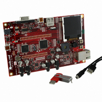
KIT EVAL LPC1768 CR
Manufacturer
NXP Semiconductors
Type
MCUr
Datasheet
1.OM11043.pdf
(79 pages)
Specifications of OM11035
Contents
Board and software
For Use With/related Products
LPC1768
Lead Free Status / RoHS Status
Lead free / RoHS Compliant
Other names
568-4815


NXP Semiconductors
LPC1769_68_67_66_65_64_63
Product data sheet
14.4 Standard I/O pin configuration
order to keep the noise coupled in via the PCB as small as possible. Also parasitics
should stay as small as possible. Values of C
accordingly to the increase in parasitics of the PCB layout.
Figure 35
The default configuration for standard I/O pins is input with pull-up enabled. The weak
MOS devices provide a drive capability equivalent to pull-up and pull-down resistors.
Fig 35. Standard I/O pin configuration with analog input
•
•
•
•
•
as digital output
as analog input
as digital input
pin configured
pin configured
pin configured
Digital output driver: Open-drain mode enabled/disabled
Digital input: Pull-up enabled/disabled
Digital input: Pull-down enabled/disabled
Digital input: Repeater mode enabled/disabled
Analog input
driver
shows the possible pin modes for standard I/O pins with analog input function:
All information provided in this document is subject to legal disclaimers.
open-drain enable
repeater mode
output enable
analog input
Rev. 6.01 — 11 March 2011
data output
data input
enable
LPC1769/68/67/66/65/64/63
pull-down enable
pull-up enable
select analog input
x1
and C
32-bit ARM Cortex-M3 microcontroller
x2
should be chosen smaller
V
V
DD
DD
strong
pull-up
strong
pull-down
weak
pull-up
weak
pull-down
© NXP B.V. 2011. All rights reserved.
V
ESD
DD
ESD
V
SS
002aaf272
70 of 79
PIN
Related parts for OM11035
Image
Part Number
Description
Manufacturer
Datasheet
Request
R

Part Number:
Description:
NXP Semiconductors designed the LPC2420/2460 microcontroller around a 16-bit/32-bitARM7TDMI-S CPU core with real-time debug interfaces that include both JTAG andembedded trace
Manufacturer:
NXP Semiconductors
Datasheet:

Part Number:
Description:
NXP Semiconductors designed the LPC2458 microcontroller around a 16-bit/32-bitARM7TDMI-S CPU core with real-time debug interfaces that include both JTAG andembedded trace
Manufacturer:
NXP Semiconductors
Datasheet:
Part Number:
Description:
NXP Semiconductors designed the LPC2468 microcontroller around a 16-bit/32-bitARM7TDMI-S CPU core with real-time debug interfaces that include both JTAG andembedded trace
Manufacturer:
NXP Semiconductors
Datasheet:
Part Number:
Description:
NXP Semiconductors designed the LPC2470 microcontroller, powered by theARM7TDMI-S core, to be a highly integrated microcontroller for a wide range ofapplications that require advanced communications and high quality graphic displays
Manufacturer:
NXP Semiconductors
Datasheet:
Part Number:
Description:
NXP Semiconductors designed the LPC2478 microcontroller, powered by theARM7TDMI-S core, to be a highly integrated microcontroller for a wide range ofapplications that require advanced communications and high quality graphic displays
Manufacturer:
NXP Semiconductors
Datasheet:
Part Number:
Description:
The Philips Semiconductors XA (eXtended Architecture) family of 16-bit single-chip microcontrollers is powerful enough to easily handle the requirements of high performance embedded applications, yet inexpensive enough to compete in the market for hi
Manufacturer:
NXP Semiconductors
Datasheet:
Part Number:
Description:
The XA-S3 device is a member of Philips Semiconductors? XA(eXtended Architecture) family of high performance 16-bitsingle-chip microcontrollers
Manufacturer:
NXP Semiconductors
Datasheet:

Part Number:
Description:
The NXP BlueStreak LH75401/LH75411 family consists of two low-cost 16/32-bit System-on-Chip (SoC) devices
Manufacturer:
NXP Semiconductors
Datasheet:
Part Number:
Description:
The NXP LPC3130/3131 combine an 180 MHz ARM926EJ-S CPU core, high-speed USB2
Manufacturer:
NXP Semiconductors
Datasheet:
Part Number:
Description:
The NXP LPC3141 combine a 270 MHz ARM926EJ-S CPU core, High-speed USB 2
Manufacturer:
NXP Semiconductors
Part Number:
Description:
The NXP LPC3143 combine a 270 MHz ARM926EJ-S CPU core, High-speed USB 2
Manufacturer:
NXP Semiconductors

Part Number:
Description:
The NXP LPC3152 combines an 180 MHz ARM926EJ-S CPU core, High-speed USB 2
Manufacturer:
NXP Semiconductors
Part Number:
Description:
The NXP LPC3154 combines an 180 MHz ARM926EJ-S CPU core, High-speed USB 2
Manufacturer:
NXP Semiconductors

Part Number:
Description:
Standard level N-channel enhancement mode Field-Effect Transistor (FET) in a plastic package using NXP High-Performance Automotive (HPA) TrenchMOS technology
Manufacturer:
NXP Semiconductors
Datasheet: