32305 Parallax Inc, 32305 Datasheet - Page 6
32305
Manufacturer Part Number
32305
Description
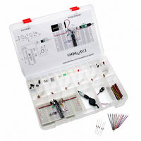
KIT EDUCATION PROPELLER
Manufacturer
Parallax Inc
Series
Propeller™r
Type
MCUr
Specifications of 32305
Contents
Propeller DIP Plus Kit, Prop Plug, PE Kit Project Parts, Breadboards and Storage Box
Product
Microcontroller Accessories
Lead Free Status / RoHS Status
Contains lead / RoHS non-compliant
For Use With/related Products
P8X32A
For Use With
130-32000 - KIT PROPELLER EDU PROJECT PARTS130-32305 - KIT PROPELLER DIP PLUS122-32000 - MANUAL PROPELLER
Lead Free Status / RoHS Status
Lead free / RoHS Compliant, Contains lead / RoHS non-compliant


The column adjacent to the red lines has two separate metal brackets underneath instead of just one.
The upper twelve sockets next to the red line are grouped together, but are not connected to the lower
twelve, and the break in the red line next indicates the break in continuity. The breadboard is designed
this way to accommodate two separate voltage supplies on the same power rail. This feature is not
used now, so all the positive power rails are shorted together with jumper wires. In later labs, you
may end up removing one or more jumpers for dual supply applications.
Power Supply
Socket the Propeller Chip
!
Make a printout of Figure 3, and verify each connection by drawing over it with a highlighter
pen after you have checked your wiring against the diagram, matching the coordinates of
each socket against the coordinates shown in the figure.
Verify that the LM2940 5 V regulator output capacitor’s negative terminal is connected to
(BLACK, 1) and that the LM2937 3 V regulator’s output capacitor’s negative terminal is
plugged into (K, 6) or (K, 7)
Verify that the Power LED’s anode terminal is connected to (RED, 10).
Connect the battery to the battery holder as shown in Figure 3. The power LED should glow
brightly. If it does not, unplug it immediately and go to Troubleshooting entry (2) on page 11.
If you have a voltmeter, make sure to test the voltage difference between the four red/black
vertical power rails.
Troubleshooting entry (3) on page 11.
If you have an oscilloscope, examine the total power supply noise. With a 9 V battery input,
it should fall in the 50 mV neighborhood. (Example settings: 10 mV x 10 ms / division, AC
coupled, Auto Store enabled to capture and hold transients for several minutes.) What
happens to the total noise if you place the 0.47 µF capacitor across the power rails?
Disconnect the battery from the clip!
Identify the orientation of the chip’s and sticker’s reference notches against Figure 3.
Affix the pinout sticker to the Propeller chip, making sure that the reference notch on the
sticker is oriented the same way as the reference notch on the chip.
Disconnect both the battery and the Propeller Plug.
Plug the Propeller chip into the breadboard, verifying its orientation as shown in Figure 3.
Plug in the battery and verify that the LED power light glows brightly, as in your earlier
battery test. If it does not, disconnect the battery immediately, and go to Troubleshooting
entry (4) on page 11.
Vss and GND; Vdd and 3.3V: The Propeller chip’s GND pin is referred to as Vss in the Propeller Manual; Vdd
is +3.3 V.
WARNING: Reverse voltage across the electrolytic capacitors can cause them to rupture or in some cases
explode. The electrolytic capacitor’s negative terminals (denoted by a stripe with negative signs) should
always be connected a lower voltage than their positive terminals.
terminals should be connected to the PE Platform’s negative power rail. This power rail is connected directly
to the battery supply’s negative terminal.
The 0.47 µF capacitor should be placed across the 9 V power input if you are using a 6-9 VDC supply
that plugs into the wall.
Copyright © Parallax Inc. ● PE Platform Setup v1.0 ● 11/2/2006 ● Page 6 of 12
Each should measure 3.3 V.
If the voltage is incorrect, go to
The electrolytic capacitors’ negative
Related parts for 32305
Image
Part Number
Description
Manufacturer
Datasheet
Request
R


Part Number:
Description:
Microcontroller Modules & Accessories DISCONTINUED BY PARALLAX
Manufacturer:
Parallax Inc

Part Number:
Description:
BOOK UNDERSTANDING SIGNALS
Manufacturer:
Parallax Inc
Datasheet:


Part Number:
Description:
COMPETITION RING FOR SUMOBOT
Manufacturer:
Parallax Inc
Datasheet:


Part Number:
Description:
TEXT INFRARED REMOTE FOR BOE-BOT
Manufacturer:
Parallax Inc
Datasheet:
Part Number:
Description:
BOARD EXPERIMENT+LCD NX-1000
Manufacturer:
Parallax Inc
Datasheet:

Part Number:
Description:
CONTROLLER 16SERVO MOTOR CONTROL
Manufacturer:
Parallax Inc
Datasheet:

Part Number:
Description:
BASIC STAMP LOGIC ANALYZER
Manufacturer:
Parallax Inc
Datasheet:

Part Number:
Description:
IC MCU 2K FLASH 50MHZ SO-18
Manufacturer:
Parallax Inc
Datasheet: