CY3684 Cypress Semiconductor Corp, CY3684 Datasheet - Page 19

CY3684
Manufacturer Part Number
CY3684
Description
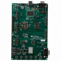
KIT DEVELOPMENT EZ-USB FX2LP
Manufacturer
Cypress Semiconductor Corp
Series
EZ-USB FXr
Type
MCUr
Datasheet
1.CY3684.pdf
(28 pages)
Specifications of CY3684
Contents
2 Boards, Cables, CD
Silicon Manufacturer
Cypress
Application Sub Type
USB
Kit Application Type
Interface
Silicon Core Number
CY7C68013A-128AXC
Features
FX2LP Development Kit
Silicon Family Name
EZ-USB FX2LP
Rohs Compliant
No
Lead Free Status / RoHS Status
Contains lead / RoHS non-compliant
For Use With/related Products
CY7C68013A-128AC, CY7C64713-128AC
Lead Free Status / RoHS Status
Contains lead / RoHS non-compliant
Other names
428-1677
CY3684
Q2204408
CY3684
Q2204408
U9 has the group address 0100, and is strapped to unit address 000. Therefore to read the switch
values, 8051 firmware sends a control byte of 01000001 (the LSB indicates a read operation), and
then reads the data byte.
4.10 Indicators—Power and Breakpoint
LED D1 is connected to the PCB 5 volt supply, which is normally supplied from the USB cable
(VBUS pin). Alternatively, JP2 may be removed and external 5 volt power can be applied to JP2
pin 1. In either case, D1 indicates the presence of the 5 volt power.
LED D6 is connected to the 3.3 volt voltage regulator output.
LED D7 is connected to the EZ-USB BKPT (Breakpoint) pin. When using the Keil software devel-
opment tools, this green LED indicates that the EZ-USB Development Board has enumerated,
and the Keil monitor has loaded and started running.
4.11 General Purpose Indicators
A portion of the GAL (U2) decodes 8051 reads to certain external memory addresses to turn the
four general-purpose indicators D2-D5 on and off. The following figure shows the positions of the
four indicator LEDS, and a table of the external 8051 addresses which are read to turn them on
and off. Note that the four jumpers above the LEDS must be installed to use this feature. These
jumpers connect the LEDS to four GAL outputs.
Note: The CLKOUT signal is used as a clock to latch the LED output signals from the GAL. If
CLKOUT is disabled, the LEDs will not update.
NOTE: If you wish to use the LEDS for other purposes, for example to wire to other PC board sig-
nals for observation, first remove the shorting plug to disconnect the LED from the GAL. The LED
terminal is the bottom pin of the connector, and the GAL I/O pin is the top pin.
EZ-USB Development Board
Bit
0
1
2
3
Switch
S2
S3
S4
S5
Page -15


