TOOLSTICKUNISK Silicon Laboratories Inc, TOOLSTICKUNISK Datasheet
TOOLSTICKUNISK
Specifications of TOOLSTICKUNISK
Available stocks


Related parts for TOOLSTICKUNISK


TOOLSTICKUNISK Summary of contents
Page 1
Handling Recommendations To enable development, the ToolStick Base Adapter and daughter cards are distributed without any protective plastics. To prevent ...
Page 2
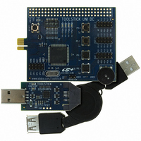
... Contents The ToolStickUniDC kit contains the following items: ToolStick University Daughter Card The ToolStickUniSK Starter Kit includes the following items: ToolStick Base Adapter ToolStick University Daughter Card 3-foot USB extension cable A ToolStick daughter card requires a ToolStick Base Adapter to communicate with the PC. If the daughter card was not purchased as part of a Starter Kit, ToolStick Base Adapters can be purchased separately at www ...
Page 3
Power LED Prototyping Area Reset Switch C8051F020 Analog I/O Header 22.1184 MHz Crystal Figure 3. ToolStick University Daughter Card (Rev 002) 4. Getting Started The necessary software to download, debug, and communicate with the target microcontroller must be downloaded from ...
Page 4
Software Overview 5.1. Silicon Laboratories IDE The Silicon Laboratories IDE integrates a source-code editor, source-level debugger, and an in-system Flash programmer. See "6. ToolStick University Daughter Card ...
Page 5
Figure 4. Configuration Wizard 2 Utility The Configuration Wizard 2 utility helps accelerate development by automatically generating initialization source code to configure and enable the on-chip resources needed for most design projects. In just a few steps, the wizard creates ...
Page 6
5.5. ToolStick Virtual Tools The ToolStick Virtual Tools include the following applications: ToolStick Terminal ToolStick Virtual LCD ToolStick Virtual Oscilloscope The ToolStick Terminal program provides the standard terminal ...
Page 7
ToolStick University Daughter Card Demo The ToolStick Virtual Tools download package includes a simple code example. The example described in this section is titled UniDC_FeaturesDemo. The purpose of this example is to guide a new user through the features ...
Page 8
6.2. Connecting to the Device and Downloading Firmware This section describes how to open the IDE, open and build a project, connect to a device, and download the ...
Page 9
Running and Stopping Code Execution Once the IDE is connected to the device and the firmware is loaded, the IDE can start and stop the code execution. The following steps can be performed using the buttons on the toolbar ...
Page 10
the debug window, change the value of P74OUT to 0x00. This value turns off all four LEDs on P5[7:4 write this new value to ...
Page 11
Scroll to the main function (line 69) and right-click on the variable “Button_Press_Count”. In the context menu that appears, select “Add Button_Press_Count to Watch” and then choose “Default.” On the right-hand portion of the IDE, the watch window appears ...
Page 12
6.6. Setting and Running to Breakpoints Silicon Laboratories microcontroller devices support up to four hardware breakpoints. A breakpoint is associated with a specific line of code. When the ...
Page 13
Single-Stepping Through Firmware The IDE supports the ability to single-step through firmware one assembly instruction at a time. The IDE reads the Flash from the device, converts the instructions to assembly and displays them in a disassembly window. The ...
Page 14
Additional Demo Examples In addition to the UniDC_FeaturesDemo example firmware, the ToolStick download package also includes a demo project called UniDC_VirtualTools_Demo. The instructions for running this demo ...
Page 15
ToolStick University Daughter Card Schematic ToolStickUniDC Rev. 0.1 15 ...
Page 16
... Should Buyer purchase or use Silicon Laboratories products for any such unintended or unauthorized ap- plication, Buyer shall indemnify and hold Silicon Laboratories harmless against all claims and damages. Silicon Laboratories and Silicon Labs are trademarks of Silicon Laboratories Inc. Other products or brandnames mentioned herein are trademarks or registered trademarks of their respective holders. ...