TOOLSTICKUNISK Silicon Laboratories Inc, TOOLSTICKUNISK Datasheet - Page 14
TOOLSTICKUNISK
Manufacturer Part Number
TOOLSTICKUNISK
Description
KIT UNIVERSITY TOOLSTICK STARTER
Manufacturer
Silicon Laboratories Inc
Series
ToolStickr
Type
MCUr
Datasheet
1.TOOLSTICKUNIDC.pdf
(16 pages)
Specifications of TOOLSTICKUNISK
Contents
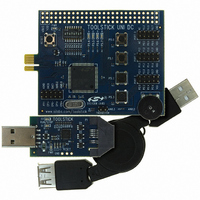
ToolStick base adapter, daughter card and 3' USB cable
Interface Type
USB
Operating Supply Voltage
2.7 V to 3.6 V
Lead Free Status / RoHS Status
Contains lead / RoHS non-compliant
For Use With/related Products
-
Lead Free Status / Rohs Status
Lead free / RoHS Compliant
Other names
336-1433
Available stocks
Company
Part Number
Manufacturer
Quantity
Price
Company:

Part Number:
TOOLSTICKUNISK
Manufacturer:
Silicon Labs
Quantity:
135


To o l St i c k U n i D C
7. Additional Demo Examples
In addition to the UniDC_FeaturesDemo example firmware, the ToolStick download package also includes a
demo project called UniDC_VirtualTools_Demo. The instructions for running this demo can be found at the top of
the source file. The ToolStick Virtual Tools are described in “AN333: ToolStick Virtual Tools User’s Guide”.
The project and source files for the demos can be found in the C:\SiLabs\MCU\ToolStick\UniversityDC\Firmware\
default directory.
8. Using the ToolStick University Daughter Card as a Development Platform
The prototyping area on the ToolStick University Daughter Card makes it easy to interface to external hardware.
Ports P0, P1, and P2 are available at the headers. Also available are the analog input/output signals at header J5.
Wires can be soldered between components in the prototyping area and the headers to add interface circuitry.
8.1. C8051F020 Pin Connections
It is important to note that if external hardware is being added, some of the existing components on the board can
interfere with the signaling. The following is a list of port pins on the C8051F020 MCU that are connected to other
components:
See the daughter card schematic in Figure 17 for more information.
9. Board Revision Information
Revision SA-TS003PCB-001 of the ToolStick University Daughter card has the labels for the CP0- and CP1- pins
swapped in the header, J5. This silk-screen error has been fixed on revision SA-TS003PCB-002. Figure 3 on page
3 shows the revised board with the labels in the correct positions. The revision number is located on the back side
of the daughter card.
10. Information Locations
Example source code is installed by default in the “C:\SiLabs\MCU\ToolStick\UniversityDC\Firmware” directory
during the ToolStick installation.
Documentation
C:\SiLabs\MCU\ToolStick\Documentation and the C:\SiLabs\MCU\ToolStick\UniversityDC\Documentation default
directories.
The installer for the ToolStick Virtual Tools software is available at www.silabs.com/mcuniversity.
14
P0.0, P0.1—These pins are connected directly to the ToolStick Base Adapter for UART communication. These
two pins are not available on the header labeled PORT 0 (J1).
P3.6, P3.7—These pins are connected directly to the ToolStick Base Adapter’s GPIO pins for use as UART
handshaking signals. The ToolStick Terminal included in the Virtual Tools application configures the GPIO pins
on the Base Adapter as RTS/CTS handshaking pins. This means that the pin, P3.7 (CTS), should be configured
as push-pull output, and P3.6 (RTS) should be configured as open-drain input on the ToolStick University
daughter card.
P5[3:0]—These four pins are connected to push-button switches on the daughter card. The series resistors,
R21 through R24, can be removed to disconnect the push-button switch from the pin.
P5[7:4]—These four pins are connected to the cathode terminals of the green LEDs on the daughter card. The
LEDs, D1 through D4, or the series resistors, R1 through R4, can be removed to disconnect the LED from the
pin.
P4—All eight pins of port P4 are connected to the eight-bit DIP switch on the daughter card. The series
resistors, R13 through R20, can be removed to disconnect the DIP switch from the port pin.
AIN0.2—This pin is connected to the output of the potentiometer. The potentiometer can be removed to
disconnect it from the pin.
for
the
ToolStick
kit,
including
Rev. 0.1
this
User’s
Guide,
can
be
found
in
the
Related parts for TOOLSTICKUNISK
Image
Part Number
Description
Manufacturer
Datasheet
Request
R

Part Number:
Description:
KIT TOOL EVAL SYS IN A USB STICK
Manufacturer:
Silicon Laboratories Inc
Datasheet:

Part Number:
Description:
TOOLSTICK DEBUG ADAPTER
Manufacturer:
Silicon Laboratories Inc
Datasheet:

Part Number:
Description:
TOOLSTICK BASE ADAPTER
Manufacturer:
Silicon Laboratories Inc
Datasheet:

Part Number:
Description:
TOOLSTICK DAUGHTER CARD
Manufacturer:
Silicon Laboratories Inc
Datasheet:

Part Number:
Description:
TOOLSTICK DAUGHTER CARD
Manufacturer:
Silicon Laboratories Inc
Datasheet:

Part Number:
Description:
TOOLSTICK DAUGHTER CARD
Manufacturer:
Silicon Laboratories Inc
Datasheet:

Part Number:
Description:
TOOLSTICK PROGRAMMING ADAPTER
Manufacturer:
Silicon Laboratories Inc
Datasheet:

Part Number:
Description:
TOOLSTICK DAUGHTER CARD
Manufacturer:
Silicon Laboratories Inc
Datasheet:

Part Number:
Description:
KIT STARTER TOOLSTICK
Manufacturer:
Silicon Laboratories Inc
Datasheet:

Part Number:
Description:
DAUGHTER CARD TOOLSTICK F330
Manufacturer:
Silicon Laboratories Inc
Datasheet:

Part Number:
Description:
CARD DAUGHTER UNIVRSTY TOOLSTICK
Manufacturer:
Silicon Laboratories Inc
Datasheet:

Part Number:
Description:
DAUGHTER CARD TOOLSTICK F582
Manufacturer:
Silicon Laboratories Inc
Datasheet:

Part Number:
Description:
DAUGHTER CARD TOOLSTICK F500
Manufacturer:
Silicon Laboratories Inc
Datasheet:

Part Number:
Description:
DAUGHTER CARD TOOLSTICK F540
Manufacturer:
Silicon Laboratories Inc
Datasheet:

Part Number:
Description:
DAUGHTER CARD TOOLSTICK F560
Manufacturer:
Silicon Laboratories Inc
Datasheet: