DEMO9RS08KA2 Freescale Semiconductor, DEMO9RS08KA2 Datasheet
DEMO9RS08KA2
Specifications of DEMO9RS08KA2
Available stocks


Related parts for DEMO9RS08KA2

DEMO9RS08KA2 Summary of contents
Page 1
...
Page 2
...
Page 3
... DEMO9RS08KA2 Demonstration Board for Freescale MC9RS08KA2 (8-Pin DIP) User’s Manual Copyright © 2006 SofTec Microsystems Revision 1.0 ® DC01088 ...
Page 4
... THEREOF. Trademarks SofTec Microsystems is a registered trademark of SofTec Microsystems, Spa. Freescale™ and the Freescale logo are trademarks of Freescale Semiconductor, Inc. Microsoft and Windows are trademarks or registered trademarks of Microsoft Corporation registered trademark of International Business Machines Corporation. Other products and company names listed are trademarks or trade names of their respective companies. ...
Page 5
... Step-by-Step Tutorial 17 7 Internal Oscillator Trimming 19 8 Jumper and Connector Settings 21 8.1 Jumpers 21 8.2 Connectors 22 9 Troubleshooting 23 9.1 USB Driver Problems 23 9.2 Communication Problems between the PC and the Demo Board 23 9.3 “LED0” LED Always Turned On 23 DEMO9RS08KA2 User's Manual Page 3 ...
Page 6
...
Page 7
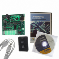
... Overview The DEMO9RS08KA2 Demonstration board has been designed for the evaluation, demonstration and debugging of the Freescale MC9RS08KA2 microcontroller. The DEMO9RS08KA2 can be used as a standalone application, or via its built-in USB-to-BDM interface. 1.2 Package Contents The DEMO9RS08KA2 package includes the following items: The DEMO9RS08KA2 evaluation board ...
Page 8
...
Page 9
... Hardware Features 2.1 Demonstration Board Features The DEMO9RS08KA2 board features MC9RS08KA2 microcontroller (in 8-pin DIP package, already programmed with a demo application—in addition, you can also use any other pin-to-pin-compatible device header connector with all of the microcontroller signals power supply section containing Power Supply Input Connector ...
Page 10
... Hardware Features 4 3 Page The DEMO9RS08KA2 Demonstration Board 2 6 ...
Page 11
... MB of available system RAM plus available hard disk space; A USB port; CD-ROM drive for installation. 3.3 Installing CodeWarrior Development Studio To install the CodeWarrior Development Studio, insert the CodeWarrior CD-ROM into your computer’s CD-ROM drive. A startup window will automatically appear. Follow the on-screen instructions. DEMO9RS08KA2 User's Manual Page 9 ...
Page 12
Software Setup 3.4 Installing SofTec Microsystems Additional Components The SofTec Microsystems Additional Components install all of the other required components to your hard drive. These components include: The Demonstration Board’s USB driver; The software plug-in for CodeWarrior; Examples; Demonstration Board’s ...
Page 13
... New Hardware Wizard” procedure, asking you to specify the driver to use for the instrument. On Windows XP (SP2) the following dialog box will appear. Select the “No, not this time” option and click the “Next >” button. 7. The following dialog box will appear. DEMO9RS08KA2 User's Manual Page 11 ...
Page 14
Hardware Setup Click the “Next >” button. 8. Depending on your Windows settings, the following warning may appear. Note: this warning is related to the fact that the USB driver used by i the Demonstration Board is not digitally signed ...
Page 15
... Click the “Finish” button to exit from the “Found New Hardware Wizard” procedure. 10. The Demonstration Board’s USB driver is now installed on your system. DEMO9RS08KA2 User's Manual Page 13 ...
Page 16
...
Page 17
... LEDs will turn on as illustrated below. Sensed Temperature between 10°C and 20°C between 20°C and 30°C Press the “SW0” push-button. The “LED0”, “LED1” and “LED2” LEDs will blink. < 10°C > 30°C DEMO9RS08KA2 User's Manual LEDs LED2 LED1 LED0 LED2 LED1 ...
Page 18
Operating Modes 5.3 Host Mode In host mode the program execution is controlled by the host PC through the “USB” connector. You can use the PC to debug the application by, for example, executing the program step by step and ...
Page 19
... Congratulations! You have successfully completed this tutorial! You can continue to experiment with the CodeWarrior user interface and discover by yourself its potentialities. For an in-depth guide of all of the user interface features, select “Help > CodeWarrior Help” from CodeWarrior Development Studio’s main menu. DEMO9RS08KA2 User's Manual Page 17 ...
Page 20
...
Page 21
... Configuration” from the “SofTec-RS08” menu. The following dialog box will appear. The MC9RS08KA2 microcontroller’s ICSTRM register and the FTRIM bit in the ICSSC register will be then programmed with a specific value which will result in the DCO output frequency specified. DEMO9RS08KA2 User's Manual Page 19 ...
Page 22
...
Page 23
... J202 J203 J302 BKGD RESET DEMO9RS08KA2 User's Manual Description/Pinout I/O ENABLE Installed: The indicated microcontroller line is connected to the indicated user I/O function (default) Not Installed: The indicated microcontroller line is not connected to the indicated user I/O function POWER SELECTION 1-2 (“USB”): ...
Page 24
Jumper and Connector Settings 8.2 Connectors Name Reference J102 PTA2 PTA0 PTA3 PTA1 VDD PTA4 GND PTA5 J103 J201 2 J301 Page 22 Description/Pinout 8-Pin Header Male Connector Replicates all of the microcontroller signals ...
Page 25
... The “LED0” LED shares the BKGD line (used for the BDM communication). If you want to use this line as a generic user I/O you must enable this feature in your application software and remove the “BKGD” jumper in the “USB TO BDM INTERFACE” section of the board. Doing so, DEMO9RS08KA2 User's Manual Page 23 ...
Page 26
... BDM communication between the host PC and the microcontroller impossible. Page 24 DEMO9RS08KA2 User's Manual ...
Page 27
...
Page 28
...