TWR-S08LH64 Freescale Semiconductor, TWR-S08LH64 Datasheet - Page 2
TWR-S08LH64
Manufacturer Part Number
TWR-S08LH64
Description
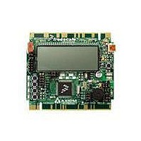
TOWER SYSTEM S08LH64
Manufacturer
Freescale Semiconductor
Type
MCUr
Datasheets
1.TWR-SENSOR-PAK.pdf
(4 pages)
2.TWR-S08LH64.pdf
(2 pages)
3.TWR-S08LH64.pdf
(19 pages)
4.TWR-S08LH64.pdf
(8 pages)
5.TWR-S08LH64.pdf
(3 pages)
Specifications of TWR-S08LH64
Contents
Board
Description/function
Tower System LCD Module
Interface Type
USB
Backlighting
No Backlighting
Data Bus Width
8 bit
Module Size (w X H X T)
3.55 in x 3.2 in
Number Of Segments
2 x 28
Operating Supply Voltage
5 V
Operating Voltage
3.3 V
Product
Display Modules
Software
Software Included
Touch Panel
No Touch Panel
Silicon Manufacturer
Freescale
Core Architecture
HCS08
Core Sub-architecture
HCS08
Silicon Core Number
MC9S08
Silicon Family Name
S08LH
Kit Contents
Board, Cable, CD
Rohs Compliant
Yes
For Use With/related Products
Freescale Tower System
Lead Free Status / RoHS Status
Lead free / RoHS Compliant


TWR-S08LH64—Lab Tutorials 1 and 2
Introduction
The MC9S08LH64 device is Freescale’s
low-power microcontroller with an
integrated liquid crystal display (LCD) driver
and 16 bit ADC with a differential input
channel and up to 8 single-end inputs.
TWR-S08LH64 contains on-board analog
input channels that allows developers to
explore the capabilities of the powerful new
ADC module. It also contains an on-module
display that allows developers to explore
software development using the integrated
LCD driver. This Lab Tutorial guide is
designed to get you ready to develop your
next measurement and display application
using the MC9S08LH64 within minutes.
Note: This Lab Tutorial can be followed once the steps in the Quick
Start Guide, installing all of the software and documentation, have
been finalized.
Lab Using Quick Start Code,
Open CodeWarrior and the
Project
This lab will highlight the capabilities of
the MC9S08LH64 microcontroller with the
application provided by the Quick Start Lab.
Pushing switch SW2 will step you through
these these four states.
State 1. Low power operation with time display
State 2. Potentiometer vs. light sensor
State 3. Accelerometer demo, X, Y and Z output
State 4. ADC demo: When in the ADC demo,
1. Install software and tools as directed in the
2. Open CodeWarrior for microcontrollers. From
3. Choose the “Start Using CodeWarrior”
4. Using CodeWarrior, click File > Open and
Lab Tutorials for TWR-S08LH64
STEP
Quick Start Guide.
Windows start menu. You can locate it using
“Programs > Freescale CodeWarrior > CW
for Microcontroller 6.3 > CodeWarriorIDE”
button.
open the PE_LH64 Quick_Start.mcp file
from the directory on your c:\ where you
unzipped the compressed projects. This is the
Quick Start project which uses CodeWarrior’s
Processor Expert for device initialization.
1
comparison
to SCI
pushing SW4 will increment the
channel converted and displayed
Explore Project Window of Quick
Start Code
Figure 3 illustrates the “Processor
Expert” and “Files” tabs.
Figure 3
There are four tabs in the project window:
File, Link Order, Target and Processor
Expert. Each tab displays the contents of
the project with respect to the context of the
tab selected. The user code is displayed in
the Files tab.
Set Up TWR-S08LH64 Module
1. Connect the 10-pin connector to the 10-pin
2. Connect an RS232 cable from the DB9 pigtail
Figure 4
STEP
STEP
Processor Expert
header on the module labeled COM PORT and
J3 (see Figure 4). During states 2, 3 and 4,
data is sent from the SCI port on the MCU to
the terminal console on your computer.
to your computer serial port.
2
3
Files
Start P&E Toolkit Application and
Enter the Programmer/Debugger
1. Open P&E Multilink Toolkit Launch Pad and
2. Start a terminal console and configure your
3. Using CodeWarrior, compile and program
4. If the MCU is in low-power stop mode you
Figure 5
5. When the message, “Loading a new
Figure 6
6. When the message, “The debugger is going
Figure 7
STEP
Terminal Window. From the Windows start
menu, select “Programs > P&E Embedded
Multilink Toolkit > Toolkit Launchpad”
computer’s com port for 19200 baud, 8 bit, 1
stop, no parity.
the MC9S08LH64 microcontroller with the
application by clicking the “Debug” button
or F5 on your keyboard, launching the
programmer and the open source
BDM debugger.
may see the message “There is currently
no communication. ”Click “OK.” Re-
establish communication by hitting SW2
and under the Component > Set Connection,
set HCS08 and FSL open source BDM. This
re-establishes BDM communications.
application will stop execution of the
current one” appears, click “OK.”
to mass erase the non-volatile memory
of the current device, then reprogram the
application” appears, click “OK.”
4
Debugger Window
A new debugger environment will open.
From the main menu, choose “Run > Start/
Continue” or press the
program will be executed in real time.
Figure 8
Clock Display State
Upon power-on or reset, the LCD will flash all
segments on, then off, the buzzer will sound,
then the display will read “9LH64” and “CL.”
Next, it enters a low-power time/day display
mode. The display is initialized with a clock
value, the current temperature and a day of
the week. The MCU will keep track of time
with the TOD module running off the 32.768
watch crystal. The temperature and battery
level are measured with the ADC16 and
displayed.
Figure 9
Highlighted features include the ADC16
measurement of the internal temperature
sensor, bandgap voltage, the TOD and
LCD module operations in low-power stop
mode. While in stop mode, the LCD blinking
function is operational.
STEP
Lab
5
1
State
1
button. The
(sheet 1 of 2)
Display and Control Features
1) Press and hold SW2 for longer than two
2) Press and hold SW1 to enter set time and
Measure current: To measure the average
current of the MCU, remove the jumper
“MCU IDD” JP2 and place a current meter
between the two pins of JP2. Reset the
TWR_S08LH64 module with the Reset
button. You should measure less than 3
micro-amps
Wake up time: The MCU is currently waking
up every second and updating the seconds
counter in the software. To reduce power
consumption, the MCU wakeup time could
be changed to 60 seconds. This reduces
the times the MCU has to wake up, enter
run mode and update the time on the LCD
display.
In the file LH64_Demo.c the code to enable
60 second wake up is commented out.
In the function “void StopClock(void),”
comment out the existing line that begins
with vfnTOD_Init and remove the comment
“//” from the next line. After programmed
with this new code, the MCU will wake up
every 60 seconds. This changes from a
second to the match interrupt. Measure the
current again and compare. You may have
to close the debugger window to enable the
lower current mode.
seconds to toggle the display view between
displaying the temperature or displaying the
seconds value in the upper two display digits.
day mode. When you do this the display
temporarily displays “CL” then “SE” for Clock
Set and the hours digit begins flashing.
Set Hour: Press SW1 to decrement and SW2
to increment.
Press and hold for two seconds both SW1
and SW2 to step to the Set Minute state.
Set Minute: Press SW1 to decrement and
SW2 to increment.
Press and hold for two seconds both SW1
and SW2 to step to the Set Day state.
Set Day: Press SW1 to decrement and SW2
to increment.
Press and hold for two seconds both SW1
and SW2 to exit the set clock mode.
The display will return to the normal display
of the new time and temperature.
TOWER SYSTEM
Related parts for TWR-S08LH64
Image
Part Number
Description
Manufacturer
Datasheet
Request
R

Part Number:
Description:
Development Boards & Kits - S08 / S12 S08PT60 Tower Kit
Manufacturer:
Freescale Semiconductor
Datasheet:
Part Number:
Description:
Development Boards & Kits - S08 / S12 S08PT60Tower MCU mod
Manufacturer:
Freescale Semiconductor
Datasheet:
Part Number:
Description:
TOWER UNIVERSAL RS08/S08
Manufacturer:
Freescale Semiconductor
Datasheet:
Part Number:
Description:
K53N512CMD100 TWR Module
Manufacturer:
Freescale Semiconductor
Datasheet:
Part Number:
Description:
TWR-K53N512 Dev Kit
Manufacturer:
Freescale Semiconductor
Datasheet:

Part Number:
Description:
CONV DC/DC TRI OUT 5,15,-15V
Manufacturer:
Murata Power Solutions Inc
Datasheet:

Part Number:
Description:
CONV DC/DC TRI OUT 5,12,-12V
Manufacturer:
Murata Power Solutions Inc
Datasheet:

Part Number:
Description:
CONV DC/DC TRI OUT 5,15,-15V
Manufacturer:
Murata Power Solutions Inc
Datasheet:

Part Number:
Description:
LCD MODULE FOR TWR SYSTEM
Manufacturer:
Freescale Semiconductor
Datasheet:

Part Number:
Description:
DC/DC TH 11W 5-5/12V Triple A
Manufacturer:
Murata Power Solutions Inc
Datasheet:


Part Number:
Description:
TOWER SYSTEM PROTO
Manufacturer:
Freescale Semiconductor
Datasheet:

Part Number:
Description:
TOWER ELEVATOR BOARDS HARDWARE
Manufacturer:
Freescale Semiconductor
Datasheet: