DEMO9S08SE8 Freescale Semiconductor, DEMO9S08SE8 Datasheet - Page 2
DEMO9S08SE8
Manufacturer Part Number
DEMO9S08SE8
Description
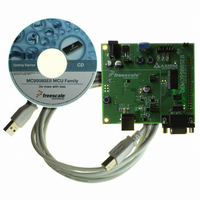
BOARD DEMO FOR SE8 FAMILY
Manufacturer
Freescale Semiconductor
Type
MCUr
Datasheets
1.DEMO9S08SE8.pdf
(2 pages)
2.DEMO9S08SE8.pdf
(2 pages)
3.DEMO9S08SE8.pdf
(8 pages)
4.DEMO9S08SE8.pdf
(13 pages)
5.DEMO9S08SE8.pdf
(1 pages)
Specifications of DEMO9S08SE8
Contents
Board and software
Processor To Be Evaluated
MC9S08SE8
Data Bus Width
8 bit
Interface Type
RS-232, USB
Operating Supply Voltage
9 V
Silicon Manufacturer
Freescale
Core Architecture
HCS08
Core Sub-architecture
HCS08
Silicon Core Number
MC9S08
Silicon Family Name
S08SE
Kit Contents
MC9S08SE8 Board, Software, Cables, Connectors
Rohs Compliant
Yes
For Use With/related Products
MC9S08SE8
Lead Free Status / RoHS Status
Lead free / RoHS Compliant


DEMO9S08SE8 Lab
This lab document applies to
DEMO9S08SE8.
Start each lab with the board powered
ON. Make sure to use only one utility at a
time, as they share the same USB source.
Familiarize yourself with these buttons:
DEMO9S08SE8—Lab Tutorial
Start/Continue (F5) button
MCU Change Wizard button
Debug button
Setting up the Demo
1. Connect the DEMO9S08SE8 demo board to the PC
2. Open both the CodeWarrior IDE and the SE8_DEMO_
3. To compile the project and program the MCU, select “P&E
5. After the MCU is programmed, start the TerminalWindow.
DEMO9S08SE8
This document explains how to set up and use the SE8_DEMO_LAB1 example application. The example application allows
the user to try out several features on Freescale’s MC9S08SE8 microcontroller.
Step
with the USB cable. The jumper configuration for this
application is:
• SW1, SW2, LED1, LED2, RV1, RZ1 jumpers are installed
• COM_SEL switches to BDM
LAB1 project.
Multilink/Cyclone Pro” from the pull-down menu beneath
the project name. Then click the debugger icon. This
will compile the project of SE8_DEMO_LAB1, launch the
debugger application and prompt the user with “Erase
and program FLASH.” Click “Yes.” The MCU is now
programmed.
exe from the DEMO9S08SE8 Toolkit directory. It will open
a terminal window connected to USB port. The USB COM
port settings must be:
• 38400 baud rate
• 8 bits
• No parity
• 1 stop bit
The demo is now ready to run.
1
Running the Demo
Now click the “RUN” button. If everything is configured
correctly, LED1 and LED2 will begin to blink alternately and
the terminal window will display the following as soon as the
demo starts:
Welcome to the World of MC9S08SE8 Demo
POR LVD, Reset Occurred
Main test menu
Please select a number to execute:
• Bus clock source
• System reset status
• Reset button
For this demo application, the reset pin on the
• Potentiometer RV1
On the demo board, the RV1 is a potentiometer. The user
• Photo sensor RZ1
On the demo board, the RZ1 is a photo sensor. As the
Step
Application V1.0
[1] Real-time clock setup
[2] TPM1 PWM setup
[3] ADC test
This demo relies on the internal clock reference to
generate bus frequency and the communications baud
rate. Therefore, the MCU’s internal clock reference has
been trimmed to 32 kHz.
After every chip reset, the terminal will display the
system reset status and state the cause or causes of the
last reset.
MC9S08SE8 is configured as an IRQ pin function. The
user can use the IRQ function to wake the MCU from low-
power mode.
can turn the RV1 to get the voltage (from 0V to 5V) on the
RV1 jumper.
intensity of the light shining on the RZ1 sensor changes,
the RZ1 jumper voltage will vary from 0V to 5V—the
lower the light, the higher the voltage. Usually, in a room
environment, the RZ1 jumper voltage is about 5V, so the
user needs a light source, such as lamp, to drive lower
RZ1 jumper voltages.
2
Demo Menu Options
The user can choose from three options to explore a few of
the MC9S08SE8’s features and go to the submenu of each
function.
To make a selection, simply type the number next to the
menu item.
[1] Real-time clock setup
Real-time clock menu:
Please select a number to execute.
These menu options let the user enable, disable and exit the
real-time clock, which is the basis of the RTC module.
When number 1 is selected, the clock is enabled and
displayed on the terminal after the current time input. Please
enter the current time according to the display: format as
HHMM (H=hour, M=minute). The clock will be displayed on
the terminal.
When number 2 is selected, the RTC is disabled, and the
clock disappears from the terminal.
[2] TPM1 PWM setup
Please select test number to execute.
These options let the user enable or disable the PWM
function of TPM1.
When number 1 is selected, LED1 connected to TPM channel
0 and LED2 connected to TPM channel 1 begin to blink
alternatively. When number 2 is selected, LED1 and LED2
stop blinking.
Step
[1]: Set up, enable and display real-time clock
[2]: Disable real-time clock
[e]: Exit real-time clock menu
TPM1 menu:
[1]: Enable TPM1
[2]: Disable TPM1
[e]: Exit TPM1 menu
3
[3] ADC menu
Please select test number to execute.
When number 1 is selected, the analog-to-digital converter
(ADC) is enabled to sample the output of RZ1. LED2
illuminates if the voltage on the photo sensor (RZ1) is higher
than 4V. If the RZ1 voltage is less than 4V, LED2 will not light
up. When number 2 is selected, the ADC is turned off.
[1]: Enable ADC to measure the RZ1
[2]: Disable ADC
[e]: Exit ADC menu
Related parts for DEMO9S08SE8
Image
Part Number
Description
Manufacturer
Datasheet
Request
R

Part Number:
Description:
Manufacturer:
STMicroelectronics
Datasheet:

Part Number:
Description:
DEMO BOARD FOR HMC6042/HMC1041Z
Manufacturer:
Honeywell Microelectronics & Precision Sensors

Part Number:
Description:
DEMO BOARD FOR HMC1042L/HMC1041Z
Manufacturer:
Honeywell Microelectronics & Precision Sensors
Datasheet:

Part Number:
Description:
KIT DEMO 4 SENSOR CHAN RS232
Manufacturer:
VTI Technologies
Datasheet:


Part Number:
Description:
DEMO: DC Power Supply, 32 Volts, 3 Amps
Manufacturer:
Tektronix
Part Number:
Description:
DEMO: Programmable DC Power Supply, 32 Volts, 3 Amps
Manufacturer:
Tektronix

Part Number:
Description:
Manufacturer:
Freescale Semiconductor, Inc
Datasheet:
Part Number:
Description:
Manufacturer:
Freescale Semiconductor, Inc
Datasheet:
Part Number:
Description:
Manufacturer:
Freescale Semiconductor, Inc
Datasheet:
Part Number:
Description:
Manufacturer:
Freescale Semiconductor, Inc
Datasheet:
Part Number:
Description:
Manufacturer:
Freescale Semiconductor, Inc
Datasheet:
Part Number:
Description:
Manufacturer:
Freescale Semiconductor, Inc
Datasheet:
Part Number:
Description:
Manufacturer:
Freescale Semiconductor, Inc
Datasheet:
Part Number:
Description:
Manufacturer:
Freescale Semiconductor, Inc
Datasheet: