DEMO9S08DZ60 Freescale Semiconductor, DEMO9S08DZ60 Datasheet
DEMO9S08DZ60
Manufacturer Part Number
DEMO9S08DZ60
Description
BOARD DEMO
Manufacturer
Freescale Semiconductor
Type
MCUr
Datasheets
1.DEMO9S08DZ60.pdf
(416 pages)
2.DEMO9S08DZ60.pdf
(1 pages)
3.DEMO9S08DZ60.pdf
(16 pages)
4.DEMO9S08DZ60.pdf
(2 pages)
5.DEMO9S08DZ60.pdf
(1 pages)
Specifications of DEMO9S08DZ60
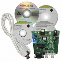
Contents
Board, Cable, CD
Processor To Be Evaluated
MC9S08DZ60
Interface Type
RS-232, USB
Silicon Manufacturer
Freescale
Core Architecture
HCS08
Core Sub-architecture
HCS08
Silicon Core Number
MC9S08
Silicon Family Name
S08D
Kit Contents
MC9S08DZ60 Board, Software, Cables, Connectors
Rohs Compliant
Yes
For Use With/related Products
MC9S08DZ60
Lead Free Status / RoHS Status
Lead free / RoHS Compliant
D E M O 9 S 0 8 D Z 6 0
R E V
1 . 0
1 2 / 2 0 0 6
Q U I C K
S T A R T
G U I D E
D O C - 0 4 0 7 - 0 2 0
DEMO9S08DZ60 QUICK START GUIDE
Introduction and Default Settings
This quick start guide will show how to connect the target board to a PC, install the correct version of CodeWarrior
Development Studio, and execute a simple demonstration program loaded in FLASH memory. The default
jumper settings for the DEMO9S08DZ60 are shown below
Figure 1: DEMO9S08DZ60 Default Settings
Install CodeWarrior Development Studio for HC(S)08 Special Edition, Version 5.1
To install CodeWarrior Development Studio for HC(S)08 Special Edition, simply refer to the provided “CodeWar-
rior Development Studio” DVD case and follow the steps in the included Quick Start Guide.
CodeWarrior Development Studios must be properly installed before attempting to connect the target board to the
host PC. Otherwise, the necessary USB drivers will not be available and the target board will not be recognized
when connected to the host PC.
Run the demo program
The DEMO9S08DZ60 is shipped with a simple demonstration program preloaded into on-chip FLASH memory.
The assembly source code (DZ60_DEMO.asm) for this demo program is located on the Axiom Support CD in the
/Examples folder. The source code is contained in the DZ60_Demo.zip file.
1. Make sure the configuration jumpers are set to the default position. Refer to Figure 1 above.
2. Connect a USB cable to an open USB port on the host PC and to the USB connector on the target board. If
necessary, follow the on-screen instructions to install the necessary USB drivers.
3. After the USB drivers are properly installed, the USB, POWER OUT, and +5V LED’s will be on.
4. LED1 and LED2 will begin to toggle.
Axiom Manufacturing, 2006. All rights reserved
Spencer Ruggles
Related parts for DEMO9S08DZ60
Image
Part Number
Description
Manufacturer
Datasheet
Request
R

Part Number:
Description:
Manufacturer:
Freescale Semiconductor, Inc
Datasheet:
Part Number:
Description:
Manufacturer:
Freescale Semiconductor, Inc
Datasheet:
Part Number:
Description:
Manufacturer:
Freescale Semiconductor, Inc
Datasheet:
Part Number:
Description:
Manufacturer:
Freescale Semiconductor, Inc
Datasheet:
Part Number:
Description:
Manufacturer:
Freescale Semiconductor, Inc
Datasheet:
Part Number:
Description:
Manufacturer:
Freescale Semiconductor, Inc
Datasheet:
Part Number:
Description:
Manufacturer:
Freescale Semiconductor, Inc
Datasheet:
Part Number:
Description:
Manufacturer:
Freescale Semiconductor, Inc
Datasheet:
Part Number:
Description:
Manufacturer:
Freescale Semiconductor, Inc
Datasheet:
Part Number:
Description:
Manufacturer:
Freescale Semiconductor, Inc
Datasheet:
Part Number:
Description:
Manufacturer:
Freescale Semiconductor, Inc
Datasheet:
Part Number:
Description:
Manufacturer:
Freescale Semiconductor, Inc
Datasheet:
Part Number:
Description:
Manufacturer:
Freescale Semiconductor, Inc
Datasheet:
Part Number:
Description:
Manufacturer:
Freescale Semiconductor, Inc
Datasheet:
Part Number:
Description:
Manufacturer:
Freescale Semiconductor, Inc
Datasheet: