DEMO9S08JS16 Freescale Semiconductor, DEMO9S08JS16 Datasheet - Page 6
DEMO9S08JS16
Manufacturer Part Number
DEMO9S08JS16
Description
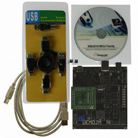
BOARD DEMO FOR JS16 FAMILY
Manufacturer
Freescale Semiconductor
Type
MCUr
Datasheets
1.DC9S08JS16.pdf
(49 pages)
2.DEMO9S08JS16.pdf
(32 pages)
3.DEMO9S08JS16.pdf
(8 pages)
4.DEMO9S08JS16.pdf
(8 pages)
5.DEMO9S08JS16.pdf
(4 pages)
Specifications of DEMO9S08JS16
Contents
2 Boards, Cable, Documentation, DVD
Processor To Be Evaluated
MC9S08JS16
Data Bus Width
8 bit
Interface Type
USB
Operating Supply Voltage
5 V
Silicon Manufacturer
Freescale
Core Architecture
HCS08
Core Sub-architecture
HCS08
Silicon Core Number
MC9S08
Silicon Family Name
S08JS
Rohs Compliant
Yes
For Use With/related Products
MC9S08JS16
Lead Free Status / RoHS Status
Lead free / RoHS Compliant


1. Insert the provided DVD into the computer. A menu
2. Click “Install PEmicro Toolkit.” This will launch the
3. Follow the on-screen instructions to complete the
For more information on the PEmicro Embedded
Multilink Toolkit read the DEMO9S08JS16
User Manual (DEMO9S08JS16 UM.pdf) included
in the “Documentation” section of the DVD.
For new and upgraded utilities to the
PEmicro Embedded Multilink Toolkit,
visit www.pemicro.com.
Connect Board to Computer
USB driver installation is a one-time required
step, to be completed after CodeWarrior
installation.
1. Remove DEMOJM baseboard and
2. Plug in the MC9S08JS16 daughter card to
3. Connect the provided A to B gray USB cable
4. The operating system will recognize your
5. Follow on-screen instructions until all USB
will appear.
toolkit installer.
installation.
DC9S08JS16 daughter card from
anti-static bags.
DEMOJM baseboard, aligning pin 1 arrows.
from a free USB port on your computer to
the USB connector on the board.
board as new hardware and will prompt you
to install the USB drivers. Choose the
recommended option to install the software
automatically. USB drivers for your board were
pre-loaded in the CodeWarrior installation.
driver installations are complete. The green
USB LED on the board should illuminate.
STEP
6
Test Board by Running
Quick Start Application
Now that you have successfully completed the
software and hardware setup, test your board
by running the Quick Start Application pre-loaded
in the microcontroller’s on-chip flash memory.
The programmed application is the HID mouse
software included in the complimentary USB
stack for MC9S08JS16. In this example, the
demo board will work as a mouse.
1. Remove the jumpers on J4.
2. Turn the SYSTEM POWER switch to the
3. Connect the provided A to mini-B black
4. Your computer will recognize the MC9S08JS16
5. Now that your board is functional, try out
“on” position. The red “Power” LED will
illuminate and the application will start.
USB cable from a free USB port on your
computer to the mini-AB USB connector
on the board.
as a HID mouse device and begin installation
(no user interaction needed). When hardware
installation is complete, the MC9S08JS16
will work as a mouse device. If the “Reset”
button is pressed and held, the PTG1
button works as the left mouse button.
If the Reset button is released, the PTG1
button acts as the right mouse button.
Similarly, the PTG2 and PTG3 buttons can
move the mouse left and up if the Reset
button his held down. When the Reset
button is released, these two buttons can
move the mouse right and down.
the labs discussed in the DEMO9S08JS16
Labs document (DEMO9S08JS16LAB)
included in the “Training” section of the
DVD. These labs will guide you step
by step through all the HID, CDC class
and USB bootloader examples included
in the complimentary USB stack for
MC9S08JS16.
STEP
7
Related parts for DEMO9S08JS16
Image
Part Number
Description
Manufacturer
Datasheet
Request
R

Part Number:
Description:
Manufacturer:
Freescale Semiconductor, Inc
Datasheet:
Part Number:
Description:
Manufacturer:
Freescale Semiconductor, Inc
Datasheet:
Part Number:
Description:
Manufacturer:
Freescale Semiconductor, Inc
Datasheet:
Part Number:
Description:
Manufacturer:
Freescale Semiconductor, Inc
Datasheet:
Part Number:
Description:
Manufacturer:
Freescale Semiconductor, Inc
Datasheet:
Part Number:
Description:
Manufacturer:
Freescale Semiconductor, Inc
Datasheet:
Part Number:
Description:
Manufacturer:
Freescale Semiconductor, Inc
Datasheet:
Part Number:
Description:
Manufacturer:
Freescale Semiconductor, Inc
Datasheet:
Part Number:
Description:
Manufacturer:
Freescale Semiconductor, Inc
Datasheet:
Part Number:
Description:
Manufacturer:
Freescale Semiconductor, Inc
Datasheet:
Part Number:
Description:
Manufacturer:
Freescale Semiconductor, Inc
Datasheet:
Part Number:
Description:
Manufacturer:
Freescale Semiconductor, Inc
Datasheet:
Part Number:
Description:
Manufacturer:
Freescale Semiconductor, Inc
Datasheet:
Part Number:
Description:
Manufacturer:
Freescale Semiconductor, Inc
Datasheet:
Part Number:
Description:
Manufacturer:
Freescale Semiconductor, Inc
Datasheet: