M5211DEMO Freescale Semiconductor, M5211DEMO Datasheet - Page 5
M5211DEMO
Manufacturer Part Number
M5211DEMO
Description
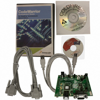
KIT DEMO FOR MCF5211
Manufacturer
Freescale Semiconductor
Series
ColdFire®r
Type
MPUr
Datasheet
1.M5211DEMO.pdf
(18 pages)
Specifications of M5211DEMO
Contents
SBC, Cables and Software
Processor To Be Evaluated
MCF521x
Data Bus Width
12 bit
Interface Type
RS-232, USB
Operating Supply Voltage
9 V
Silicon Manufacturer
Freescale
Core Architecture
Coldfire
Core Sub-architecture
Coldfire V2
Silicon Core Number
MCF52
Silicon Family Name
MCF521x
Rohs Compliant
Yes
For Use With/related Products
MCF5211, MCF5212, MCF5213
Lead Free Status / RoHS Status
Lead free / RoHS Compliant


2
To get started, please refer to the M5211 Quick Start Guide included with this development kit.
The M5211DEMO single board computer is a fully assembled, fully functional development board for the
Freescale MCF5211 microcontroller. An included serial cable, USB cable, and support software allows
you to get started quickly.
The purpose of this development board is to assist you in quickly developing an application in a known
working environment, to provide an evaluation platform, or as a control module for an embedded system.
You should be familiar with memory mapping, memory types, and embedded software design for
successful application development.
You should be familiar with the hardware and software operation of the target MCF5211 device before
beginning. If necessary, refer to the MCF5213 Integrated Microcontroller Reference Manual, included on
the support CD, for details on the operation of the MCF5211.
3
Software development requires the use of a ColdFire assembler or compiler and a host PC running a
ColdFire BDM interface. CodeWarrior 6.1 Special Edition, which is supplied with this board, allows you
to develop and debug application code and to program the flash memory.
To ensure successful application development, load and execute the application from RAM. After the
application has been completely debugged fully functional, it can be ported to flash memory. When
programmed into flash memory, the application will execute from power-on or RESET.
4
The M5211DEMO board operates in two basic modes RUN mode, or DEBUG mode. RUN mode executes
user application code from power-on or reset. DEBUG mode supports the development and debug of
applications via the integrated USB BDM. An optional BDM_PORT is provided but not installed. See
the related sections below for quickly starting the board in the desired mode of operation.
The board has been preloaded with a demonstration program that operates in the RUN mode (see the
M5211DEMO Quick Start Guide for additional information). The VDD LED is lit when power is applied
to the board and the PWR_SEL option header is set correctly. The OFF/ON switch must also be set to the
ON position.
4.1
RUN mode allows your application to execute out of flash memory when power is applied to the board or
the RESET button is pressed. Use these settings to configure the M5211DEMO board for RUN mode
using the USB bus to power the board. See
alternate power input.
Freescale Semiconductor
1. Connect a serial cable between the board and a host PC if needed.
2. Connect auxiliary equipment to board if needed.
3. Configure the board option jumpers as shown in
Getting Started
Software Development
Operating Modes
RUN Mode
Demonstration Board for Freescale MCF5211, Rev. 1
tSection 7,
“Power,” for details on configuring the board for
Table
2.
Getting Started
5
Related parts for M5211DEMO
Image
Part Number
Description
Manufacturer
Datasheet
Request
R

Part Number:
Description:
Manufacturer:
Freescale Semiconductor, Inc
Datasheet:
Part Number:
Description:
Manufacturer:
Freescale Semiconductor, Inc
Datasheet:
Part Number:
Description:
Manufacturer:
Freescale Semiconductor, Inc
Datasheet:
Part Number:
Description:
Manufacturer:
Freescale Semiconductor, Inc
Datasheet:
Part Number:
Description:
Manufacturer:
Freescale Semiconductor, Inc
Datasheet:
Part Number:
Description:
Manufacturer:
Freescale Semiconductor, Inc
Datasheet:
Part Number:
Description:
Manufacturer:
Freescale Semiconductor, Inc
Datasheet:
Part Number:
Description:
Manufacturer:
Freescale Semiconductor, Inc
Datasheet:
Part Number:
Description:
Manufacturer:
Freescale Semiconductor, Inc
Datasheet:
Part Number:
Description:
Manufacturer:
Freescale Semiconductor, Inc
Datasheet:
Part Number:
Description:
Manufacturer:
Freescale Semiconductor, Inc
Datasheet:
Part Number:
Description:
Manufacturer:
Freescale Semiconductor, Inc
Datasheet:
Part Number:
Description:
Manufacturer:
Freescale Semiconductor, Inc
Datasheet:
Part Number:
Description:
Manufacturer:
Freescale Semiconductor, Inc
Datasheet:
Part Number:
Description:
Manufacturer:
Freescale Semiconductor, Inc
Datasheet: