C8051F912DK Silicon Laboratories Inc, C8051F912DK Datasheet - Page 11
C8051F912DK
Manufacturer Part Number
C8051F912DK
Description
KIT DEV FOR C8051F91X/C8051F90X
Manufacturer
Silicon Laboratories Inc
Type
MCUr
Specifications of C8051F912DK
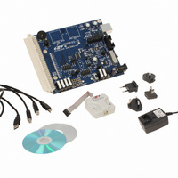
Contents
Board, Batteries, Cables, CD, Power Adapter, USB Debug Adapter
Product
Microcontroller Modules
Core Processor
C8051F9xx
Clock Speed
32.768 KHz
Interface Type
UART
Operating Supply Voltage
1.8 V to 3.6 V
Lead Free Status / RoHS Status
Contains lead / RoHS non-compliant
For Use With/related Products
C8051F91x/0x
Lead Free Status / RoHS Status
Contains lead / RoHS non-compliant
Other names
336-1854
Available stocks
Company
Part Number
Manufacturer
Quantity
Price
Company:

Part Number:
C8051F912DK
Manufacturer:
Silicon Labs
Quantity:
135


C8051F912-DK
6. Example Source Code
Example source code and register definition files are provided in the “SiLabs\MCU\Examples\C8051F91x_90x\”
default directory during IDE installation. These files may be used as a template for code development. Example
applications include a blinking LED example which configures the green LED on the target board to blink at a fixed
rate.
6.1. Register Definition Files
Register definition files C8051F912.inc and C8051F912_defs.h define all SFR registers and bit-addressable
control/status bits. A macro definition header file compiler_defs.h is also included, and is required to be able to use
the
C8051F912_defs.h
header
file
with
various
tool
chains.
These
files
are
installed
into
the
“SiLabs\MCU\Examples\C8051F91x_90x\Header_Files\” directory during IDE installation by default. The register
and bit names are identical to those used in the C8051F91x-C8051F90x data sheet. These register definition files
are also installed in the default search path used by the Keil Software 8051 tools. Therefore, when using the Keil
8051 tools included with the development kit (A51, C51), it is not necessary to copy a register definition file to each
project’s file directory.
6.2. Blinking LED Example
The
example
source
files
F91x_Blinky.asm
and
F91x_Blinky.c
installed
in
the
default
directory
“SiLabs\MCU\Examples\C8051F91x_90x\Blinky” show examples of several basic C8051F912 functions. These
include disabling the watchdog timer (WDT), configuring the Port I/O crossbar, configuring a timer for an interrupt
routine, initializing the system clock, and configuring a GPIO port pin. When compiled/assembled and linked this
program flashes the green LED on the C8051F912 Target Board about five times a second using the interrupt
handler with a C8051F912 timer.
6.3. Touch Sensitive Switch Example
The example source file F91x_CapTouchSense_Switch.c demonstrates the configuration and usage of the touch
sensitive (contactless) switches located on P1.0 and P1.1. Refer to the source file for step-by-step instructions to
build
and
test
this
example.
This
is
installed
in
the
“SiLabs\MCU\Examples\C8051F91x_90x\
CapTouchSense_Switch” directory by default.
Rev. 0.1
11
Related parts for C8051F912DK
Image
Part Number
Description
Manufacturer
Datasheet
Request
R

Part Number:
Description:
SMD/C°/SINGLE-ENDED OUTPUT SILICON OSCILLATOR
Manufacturer:
Silicon Laboratories Inc
Part Number:
Description:
Manufacturer:
Silicon Laboratories Inc
Datasheet:
Part Number:
Description:
N/A N/A/SI4010 AES KEYFOB DEMO WITH LCD RX
Manufacturer:
Silicon Laboratories Inc
Datasheet:
Part Number:
Description:
N/A N/A/SI4010 SIMPLIFIED KEY FOB DEMO WITH LED RX
Manufacturer:
Silicon Laboratories Inc
Datasheet:
Part Number:
Description:
N/A/-40 TO 85 OC/EZLINK MODULE; F930/4432 HIGH BAND (REV E/B1)
Manufacturer:
Silicon Laboratories Inc
Part Number:
Description:
EZLink Module; F930/4432 Low Band (rev e/B1)
Manufacturer:
Silicon Laboratories Inc
Part Number:
Description:
I°/4460 10 DBM RADIO TEST CARD 434 MHZ
Manufacturer:
Silicon Laboratories Inc
Part Number:
Description:
I°/4461 14 DBM RADIO TEST CARD 868 MHZ
Manufacturer:
Silicon Laboratories Inc
Part Number:
Description:
I°/4463 20 DBM RFSWITCH RADIO TEST CARD 460 MHZ
Manufacturer:
Silicon Laboratories Inc
Part Number:
Description:
I°/4463 20 DBM RADIO TEST CARD 868 MHZ
Manufacturer:
Silicon Laboratories Inc
Part Number:
Description:
I°/4463 27 DBM RADIO TEST CARD 868 MHZ
Manufacturer:
Silicon Laboratories Inc
Part Number:
Description:
I°/4463 SKYWORKS 30 DBM RADIO TEST CARD 915 MHZ
Manufacturer:
Silicon Laboratories Inc
Part Number:
Description:
N/A N/A/-40 TO 85 OC/4463 RFMD 30 DBM RADIO TEST CARD 915 MHZ
Manufacturer:
Silicon Laboratories Inc
Part Number:
Description:
I°/4463 20 DBM RADIO TEST CARD 169 MHZ
Manufacturer:
Silicon Laboratories Inc