C8051F700DK Silicon Laboratories Inc, C8051F700DK Datasheet - Page 6
C8051F700DK
Manufacturer Part Number
C8051F700DK
Description
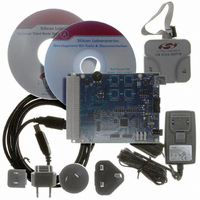
DEV KIT FOR C8051F700
Manufacturer
Silicon Laboratories Inc
Type
MCUr
Datasheets
1.C8051F700-TB.pdf
(1 pages)
2.C8051F700-TB.pdf
(306 pages)
3.C8051F700-TB.pdf
(18 pages)
Specifications of C8051F700DK
Contents
Board, Cables, CD, Debugger, Power Supply
Processor To Be Evaluated
C8051F7x
Processor Series
C8051F7xx
Interface Type
USB
Operating Supply Voltage
3.3 V
Lead Free Status / RoHS Status
Lead free / RoHS Compliant
For Use With/related Products
C8051F7xx
Lead Free Status / Rohs Status
Lead free / RoHS Compliant
Other names
336-1635


C8051F700-DK
5. Example Source Code
Example source code and register definition files are provided in the “SiLabs\MCU\Examples\C8051F70x_71x\”
directory during IDE installation. These files may be used as a template for code development. The comments in
each example file indicate which development tool chains were used when testing.
5.1. Register Definition Files
Register definition files C8051F70x.inc, C8051F70x_defs.h and compiler_defs.h define all SFR registers and bit-
addressable control/status bits. They are installed into the “SiLabs\MCU\Examples\C8051F70x_71x\” directory
during IDE installation. The register and bit names are identical to those used in the C8051F70x datasheet.
5.2. Blinking LED Example
The example source files
“SiLabs\MCU\Examples\C8051F70x_71x\Blinky” show examples of several basic C8051F700 functions. These
include disabling the watchdog timer (WDT), configuring the Port I/O crossbar, configuring a timer for an interrupt
routine, initializing the system clock, and configuring a GPIO port pin. When compiled/assembled and linked this
program flashes the green LED (DS3) on the C8051F700 Target Board about five times a second using the
interrupt handler with a C8051F700 timer.
5.3. Capacitive Sense Switch Example
The example source file F70x_CS0.c demonstrates the configuration and usage of the capacitive sense switches
located on P2.0 through P2.3. Refer to the source file for step-by-step instructions to build and test this example.
This is installed in the “SiLabs\MCU\Examples\C8051F70x_71x\ CS0\” directory by default.
5.4. QuickSense™ Firmware API Example
The
c:\Silabs\MCU\QuickSense_Studio\Kits\F700_TargetBoard. The firmware uses the QuickSense Firmware API to
measure capacitance on the sensing pads and application layer code adjusts the brightness of the target board’s
LED whenever the user presses a sensing pad. The firmware provides the following functionality:
6
Stores measured capacitance values from 4 sensor pads.
Compares measured capacitance values against calibrated thresholds to determine if buttons have been
pressed.
If a button’s “active” or “inactive” threshold has been crossed, the API signals an application layer routine
adjusts the brightness of the board’s LED.
Using the Serial Interface part of the QuickSense Firmware API , the firmware transmits measured capacitance
values across the CP210x USB-to-UART serial interface to the QuickSense development and display tools.
Baselining algorithm reduces effects of environmental changes such as temperature and humidity on sensing
pad sensitivity.
5. Save the project when finished with the debug session to preserve the current target build configuration,
Note: To enable automatic downloading if the program build is successful select Enable automatic con-
nect/download after build in the Project
build process, the IDE will not attempt the download.
editor settings and the location of all open debug views. To save the project, select Project
As... from the menu. Create a new name for the project and click on Save.
QuickSense
Studio
F70x_Blinky.asm and
package
installs
Target Build Configuration dialog. If errors occur during the
Rev. 0.2
F70x_Blinky.c installed in the default directory
an
F700
target
board
example
Save Project
at
Related parts for C8051F700DK
Image
Part Number
Description
Manufacturer
Datasheet
Request
R

Part Number:
Description:
SMD/C°/SINGLE-ENDED OUTPUT SILICON OSCILLATOR
Manufacturer:
Silicon Laboratories Inc
Part Number:
Description:
Manufacturer:
Silicon Laboratories Inc
Datasheet:
Part Number:
Description:
N/A N/A/SI4010 AES KEYFOB DEMO WITH LCD RX
Manufacturer:
Silicon Laboratories Inc
Datasheet:
Part Number:
Description:
N/A N/A/SI4010 SIMPLIFIED KEY FOB DEMO WITH LED RX
Manufacturer:
Silicon Laboratories Inc
Datasheet:
Part Number:
Description:
N/A/-40 TO 85 OC/EZLINK MODULE; F930/4432 HIGH BAND (REV E/B1)
Manufacturer:
Silicon Laboratories Inc
Part Number:
Description:
EZLink Module; F930/4432 Low Band (rev e/B1)
Manufacturer:
Silicon Laboratories Inc
Part Number:
Description:
I°/4460 10 DBM RADIO TEST CARD 434 MHZ
Manufacturer:
Silicon Laboratories Inc
Part Number:
Description:
I°/4461 14 DBM RADIO TEST CARD 868 MHZ
Manufacturer:
Silicon Laboratories Inc
Part Number:
Description:
I°/4463 20 DBM RFSWITCH RADIO TEST CARD 460 MHZ
Manufacturer:
Silicon Laboratories Inc
Part Number:
Description:
I°/4463 20 DBM RADIO TEST CARD 868 MHZ
Manufacturer:
Silicon Laboratories Inc
Part Number:
Description:
I°/4463 27 DBM RADIO TEST CARD 868 MHZ
Manufacturer:
Silicon Laboratories Inc
Part Number:
Description:
I°/4463 SKYWORKS 30 DBM RADIO TEST CARD 915 MHZ
Manufacturer:
Silicon Laboratories Inc
Part Number:
Description:
N/A N/A/-40 TO 85 OC/4463 RFMD 30 DBM RADIO TEST CARD 915 MHZ
Manufacturer:
Silicon Laboratories Inc
Part Number:
Description:
I°/4463 20 DBM RADIO TEST CARD 169 MHZ
Manufacturer:
Silicon Laboratories Inc