C8051F530ADK Silicon Laboratories Inc, C8051F530ADK Datasheet - Page 5
C8051F530ADK
Manufacturer Part Number
C8051F530ADK
Description
KIT DEV C8051F53XA, C8051F52XA
Manufacturer
Silicon Laboratories Inc
Type
MCUr
Datasheet
1.C8051F530ADK.pdf
(18 pages)
Specifications of C8051F530ADK
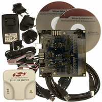
Contents
Target Board, Power Adapter, USB Debug Adapter, Cables, and Software
Processor To Be Evaluated
C8051F52xA and C8051F53xA
Interface Type
USB
Lead Free Status / RoHS Status
Lead free / RoHS Compliant
For Use With/related Products
C8051F53XA, C8051F52XA
Lead Free Status / Rohs Status
Lead free / RoHS Compliant
Other names
336-1488


4. Hardware Setup Using a USB Debug Adapter
The target board is connected to a PC running the Silicon Laboratories IDE via the USB Debug Adapter as shown
in Figure 2.
Notes:
1. Connect the USB Debug Adapter to one of the DEBUG connectors on the target board (HDR1 or HDR2)
2. Verify that shorting blocks are installed on J13 and J14 to supply power to the target devices.
3. Connect one end of the USB cable to the USB connector on the USB Debug Adapter.
4. Connect the other end of the USB cable to a USB Port on the PC.
5. Connect the ac/dc power adapter to power jack P5 on the target board.
• Use the Reset button in the IDE to reset the target when connected using a USB Debug Adapter.
• Remove power from the target board and the USB Debug Adapter before connecting or disconnecting the
ribbon cable from the target board. Connecting or disconnecting the cable when the devices have power can
damage the device and/or the USB Debug Adapter.
with the 10-pin ribbon cable. The recommended connection is to the HDR2 (connected to U2) as this micro-
controller can be connected to the CP2102 USB to UART bridge.
PC
Figure 2. Hardware Setup using a USB Debug Adapter
Cable
USB
USB Debug Adapter
Rev. 0.3
HDR2
Reset_A
C8051F530A-DK
P0.0_B
P1.6_B
P1.7_B
4
Target Board
H D R
Adapter
AC/DC
Reset_B
HDR1
5
Related parts for C8051F530ADK
Image
Part Number
Description
Manufacturer
Datasheet
Request
R

Part Number:
Description:
SMD/C°/SINGLE-ENDED OUTPUT SILICON OSCILLATOR
Manufacturer:
Silicon Laboratories Inc
Part Number:
Description:
Manufacturer:
Silicon Laboratories Inc
Datasheet:
Part Number:
Description:
N/A N/A/SI4010 AES KEYFOB DEMO WITH LCD RX
Manufacturer:
Silicon Laboratories Inc
Datasheet:
Part Number:
Description:
N/A N/A/SI4010 SIMPLIFIED KEY FOB DEMO WITH LED RX
Manufacturer:
Silicon Laboratories Inc
Datasheet:
Part Number:
Description:
N/A/-40 TO 85 OC/EZLINK MODULE; F930/4432 HIGH BAND (REV E/B1)
Manufacturer:
Silicon Laboratories Inc
Part Number:
Description:
EZLink Module; F930/4432 Low Band (rev e/B1)
Manufacturer:
Silicon Laboratories Inc
Part Number:
Description:
I°/4460 10 DBM RADIO TEST CARD 434 MHZ
Manufacturer:
Silicon Laboratories Inc
Part Number:
Description:
I°/4461 14 DBM RADIO TEST CARD 868 MHZ
Manufacturer:
Silicon Laboratories Inc
Part Number:
Description:
I°/4463 20 DBM RFSWITCH RADIO TEST CARD 460 MHZ
Manufacturer:
Silicon Laboratories Inc
Part Number:
Description:
I°/4463 20 DBM RADIO TEST CARD 868 MHZ
Manufacturer:
Silicon Laboratories Inc
Part Number:
Description:
I°/4463 27 DBM RADIO TEST CARD 868 MHZ
Manufacturer:
Silicon Laboratories Inc
Part Number:
Description:
I°/4463 SKYWORKS 30 DBM RADIO TEST CARD 915 MHZ
Manufacturer:
Silicon Laboratories Inc
Part Number:
Description:
N/A N/A/-40 TO 85 OC/4463 RFMD 30 DBM RADIO TEST CARD 915 MHZ
Manufacturer:
Silicon Laboratories Inc
Part Number:
Description:
I°/4463 20 DBM RADIO TEST CARD 169 MHZ
Manufacturer:
Silicon Laboratories Inc