C8051F530ADK Silicon Laboratories Inc, C8051F530ADK Datasheet - Page 6
C8051F530ADK
Manufacturer Part Number
C8051F530ADK
Description
KIT DEV C8051F53XA, C8051F52XA
Manufacturer
Silicon Laboratories Inc
Type
MCUr
Datasheet
1.C8051F530ADK.pdf
(18 pages)
Specifications of C8051F530ADK
Contents
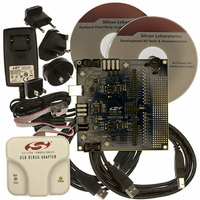
Target Board, Power Adapter, USB Debug Adapter, Cables, and Software
Processor To Be Evaluated
C8051F52xA and C8051F53xA
Interface Type
USB
Lead Free Status / RoHS Status
Lead free / RoHS Compliant
For Use With/related Products
C8051F53XA, C8051F52XA
Lead Free Status / Rohs Status
Lead free / RoHS Compliant
Other names
336-1488


C8051F530A-DK
5. Using the Keil Software 8051 Tools with the Silicon Laboratories IDE
To perform source-level debugging with the IDE, you must configure the Keil 8051 tools to generate an absolute
object file in the OMF-51 format with object extensions and debug records enabled. Build the OMF-51 absolute
object file by calling the Keil 8051 tools at the command line (e.g. batch file or make file) or by using the project
manager built into the IDE. The default configuration when using the Silicon Laboratories IDE project manager
enables object extension and debug record generation. Refer to Application Note "AN104: Integrating Keil 8051
Tools into the Silicon Labs IDE" in the “SiLabs\MCU\Documentation\ApplicationNotes” directory for additional
information on using the Keil 8051 tools with the Silicon Laboratories IDE.
To build an absolute object file using the Silicon Laboratories IDE project manager, you must first create a project.
A project consists of a set of files, IDE configuration, debug views, and a target build configuration (list of files and
tool configurations used as input to the assembler, compiler, and linker when building an output object file).
The following sections illustrate the steps necessary to manually create a project with one or more source files,
build a program, and download it to the target in preparation for debugging. (The IDE will automatically create a
single-file project using the currently open and active source file if you select Build/Make Project before a project
is defined.)
5.1. Creating a New Project
1. Select Project
2. Select File
3. Right-click on “New Project” in the Project Window. Select Add files to project. Select files in the file browser
4. For each of the files in the Project Window that you want assembled, compiled, and linked into the target build,
5. If a project contains a large number of files, the “Group” feature of the IDE can be used to organize. Right-click
5.2. Building and Downloading the Program for Debugging
1. Once all source files have been added to the target build, build the project by clicking on the Build/Make
Note: After the project has been built the first time, the Build/Make Project command will only build the files that have been
2. Before connecting to the target device, several connection options may need to be set. Open the Connection
3. Click the Connect button in the toolbar or select Debug
4. Download the project to the target by clicking the Download Code button in the toolbar.
Note: To enable automatic downloading if the program build is successful, select Enable automatic connect/download after
5. Save the project when finished with the debug session to preserve the current target build configuration, editor
6
recognized extension, such as .c, .h, or .asm, to enable color syntax highlighting.
and click Open. Continue adding files until all project files have been added.
right-click on the file name and select Add file to build. Each file will be assembled or compiled as appropriate
(based on file extension) and linked into the build of the absolute object file.
on “New Project” in the Project Window. Select Add Groups to project. Add pre-defined groups or add
customized groups. Right-click on the group name and choose Add file to group. Select files to be added.
Continue adding files until all project files have been added.
Project button in the toolbar or selecting Project
Options window by selecting Options
appropriate adapter in the “Serial Adapter” section. Next, the correct “Debug Interface” must be selected.
C8051F52xA-53xA family devices use the Silicon Labs 2-wire (C2) debug interface. Once all the selections are
made, click the OK button to close the window.
settings, and the location of all open debug views. To save the project, select Project
from the menu. Create a new name for the project and click on Save.
changed since the previous build. To rebuild all files and project dependencies, click on the Rebuild All button in the
toolbar or select Project
build in the Project
attempt the download.
→
New File to open an editor window. Create your source file(s) and save the file(s) with a
→
New Project to open a new project and reset all configuration settings to default.
→
Target Build Configuration dialog. If errors occur during the build process, the IDE will not
→
Rebuild All from the menu.
→
Connection Options . . . in the IDE menu. First, select the
→
Rev. 0.3
Build/Make Project from the menu.
→
Connect from the menu to connect to the device.
→
Save Project As . . .
Related parts for C8051F530ADK
Image
Part Number
Description
Manufacturer
Datasheet
Request
R

Part Number:
Description:
SMD/C°/SINGLE-ENDED OUTPUT SILICON OSCILLATOR
Manufacturer:
Silicon Laboratories Inc
Part Number:
Description:
Manufacturer:
Silicon Laboratories Inc
Datasheet:
Part Number:
Description:
N/A N/A/SI4010 AES KEYFOB DEMO WITH LCD RX
Manufacturer:
Silicon Laboratories Inc
Datasheet:
Part Number:
Description:
N/A N/A/SI4010 SIMPLIFIED KEY FOB DEMO WITH LED RX
Manufacturer:
Silicon Laboratories Inc
Datasheet:
Part Number:
Description:
N/A/-40 TO 85 OC/EZLINK MODULE; F930/4432 HIGH BAND (REV E/B1)
Manufacturer:
Silicon Laboratories Inc
Part Number:
Description:
EZLink Module; F930/4432 Low Band (rev e/B1)
Manufacturer:
Silicon Laboratories Inc
Part Number:
Description:
I°/4460 10 DBM RADIO TEST CARD 434 MHZ
Manufacturer:
Silicon Laboratories Inc
Part Number:
Description:
I°/4461 14 DBM RADIO TEST CARD 868 MHZ
Manufacturer:
Silicon Laboratories Inc
Part Number:
Description:
I°/4463 20 DBM RFSWITCH RADIO TEST CARD 460 MHZ
Manufacturer:
Silicon Laboratories Inc
Part Number:
Description:
I°/4463 20 DBM RADIO TEST CARD 868 MHZ
Manufacturer:
Silicon Laboratories Inc
Part Number:
Description:
I°/4463 27 DBM RADIO TEST CARD 868 MHZ
Manufacturer:
Silicon Laboratories Inc
Part Number:
Description:
I°/4463 SKYWORKS 30 DBM RADIO TEST CARD 915 MHZ
Manufacturer:
Silicon Laboratories Inc
Part Number:
Description:
N/A N/A/-40 TO 85 OC/4463 RFMD 30 DBM RADIO TEST CARD 915 MHZ
Manufacturer:
Silicon Laboratories Inc
Part Number:
Description:
I°/4463 20 DBM RADIO TEST CARD 169 MHZ
Manufacturer:
Silicon Laboratories Inc