MCIMX23LCD Freescale Semiconductor, MCIMX23LCD Datasheet - Page 21
MCIMX23LCD
Manufacturer Part Number
MCIMX23LCD
Description
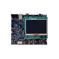
MODULE LCD IMX233 4.3" WQVGA
Manufacturer
Freescale Semiconductor
Series
i.MX23r
Type
Applications Processorsr
Datasheets
1.MCIMX23LCD.pdf
(2 pages)
2.MCIMX23LCD.pdf
(2 pages)
3.MCIMX23LCD.pdf
(29 pages)
4.MCIMX23LCD.pdf
(2 pages)
Specifications of MCIMX23LCD
Contents
Board
Processor To Be Evaluated
ARM926EJ-S
Processor Series
i.MX233
Data Bus Width
32 bit
Interface Type
RS-232, Ethernet, UART
Core
ARM926EJS
Maximum Operating Temperature
+ 50 C
Minimum Operating Temperature
- 10 C
Operating Supply Voltage
5 V
Silicon Manufacturer
Freescale
Core Architecture
ARM
Core Sub-architecture
ARM9
Silicon Core Number
I.MX2
Silicon Family Name
I.MX23
Kit Contents
I.MX23 WVGA 4.3" LCD
Rohs Compliant
Yes
Tool Type
Development Kit
Cpu Core
ARM926EJ-S
For Use With/related Products
ARM926EJ-S
Lead Free Status / RoHS Status
Lead free / RoHS Compliant


The i.MX23 EVK, on the revision C of the board, is designed to allow the serial JTAG function
and the Debug UART functions to be disconnected from the CPU and used independently to
support the bring up of other prototype boards. To use this feature, the designer must have
available:
-A wire connected to the DEBUG pin of the CPU (E12).
- A wire connected to the PSWITCH pin of the CPU (B3).
- A wire connected to PWM0 (C3).
- A wire connected to PWM1 (D2).
- A wire connected to system ground.
To use the EVK to support the prototype:
1.
2.
3.
a.
b.
c.
d.
e.
4.
will automatically receive power from the EVK regulators. Any CPU operations at this time will
not affect the JATG/DUART signals. To ensure that the CPU is kept off, the BATTERY
SUPPLY switch (S12) can be moved to the right and any Li-ION battery detached from the
EVK.
The JTAG and UART connections should now work for the attached prototype board in the
same way they work for the EVK CPU.
3.3 Using the EVK to provide JTAG/UART support for
Freescale Semiconductor
Place switch S23 in the right position (TO JP122).
Connect the prototype wires to the EVK as follows:
PWM0 to JP122 Pin 1
PWM1 to JP122 pin 2
DEBUG to JP122 pin 4
PSWITCH to JP122 pin 5
GROUND to JP122 pin 6.
Ensure that 5V wall power is supplied to the board. The UART driver IC and the CPLD
Place the SJTAG DEBUG switch (S22) in the down (TO JP122) position.
custom designed prototype boards (Only on Rev C
boards)
i.MX23 EVK Hardware User’s Guide, Rev 1.1
3-3
Related parts for MCIMX23LCD
Image
Part Number
Description
Manufacturer
Datasheet
Request
R

Part Number:
Description:
Manufacturer:
Freescale Semiconductor, Inc
Datasheet:
Part Number:
Description:
Manufacturer:
Freescale Semiconductor, Inc
Datasheet:
Part Number:
Description:
Manufacturer:
Freescale Semiconductor, Inc
Datasheet:
Part Number:
Description:
Manufacturer:
Freescale Semiconductor, Inc
Datasheet:
Part Number:
Description:
Manufacturer:
Freescale Semiconductor, Inc
Datasheet:
Part Number:
Description:
Manufacturer:
Freescale Semiconductor, Inc
Datasheet:
Part Number:
Description:
Manufacturer:
Freescale Semiconductor, Inc
Datasheet:
Part Number:
Description:
Manufacturer:
Freescale Semiconductor, Inc
Datasheet:
Part Number:
Description:
Manufacturer:
Freescale Semiconductor, Inc
Datasheet:
Part Number:
Description:
Manufacturer:
Freescale Semiconductor, Inc
Datasheet:
Part Number:
Description:
Manufacturer:
Freescale Semiconductor, Inc
Datasheet:
Part Number:
Description:
Manufacturer:
Freescale Semiconductor, Inc
Datasheet:
Part Number:
Description:
Manufacturer:
Freescale Semiconductor, Inc
Datasheet:
Part Number:
Description:
Manufacturer:
Freescale Semiconductor, Inc
Datasheet:
Part Number:
Description:
Manufacturer:
Freescale Semiconductor, Inc
Datasheet: