R0K571242S000BE Renesas Electronics America, R0K571242S000BE Datasheet - Page 4
R0K571242S000BE
Manufacturer Part Number
R0K571242S000BE
Description
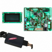
KIT DEV RSK SH7124
Manufacturer
Renesas Electronics America
Series
Renesas Starter Kits (RSK)r
Type
MCUr
Datasheets
1.R0K571242S000BE.pdf
(6 pages)
2.R0K571242S000BE.pdf
(26 pages)
3.R0K571242S000BE.pdf
(4 pages)
Specifications of R0K571242S000BE
Contents
CPU Board, LCD Display Module, E8 Emulator, Cable, QuickStart Guide and CD-ROM
For Use With/related Products
SH7124
Lead Free Status / RoHS Status
Not applicable / Not applicable


Table of Contents
Chapter 1. Preface ..................................................................................................................................................1
Chapter 2. Purpose .................................................................................................................................................2
Chapter 3. Power Supply ........................................................................................................................................3
Chapter 4. Board Layout .........................................................................................................................................4
Chapter 5. Block Diagram .......................................................................................................................................6
Chapter 6. User Circuitry.........................................................................................................................................7
Chapter 7. Modes..................................................................................................................................................12
Chapter 8. Programming Methods........................................................................................................................13
Chapter 9. Headers...............................................................................................................................................14
Chapter 10. Code Development ...........................................................................................................................17
Chapter 11. Component Placement ......................................................................................................................19
Chapter 12. Additional Information........................................................................................................................20
3.1. Requirements ...............................................................................................................................................3
3.2. Power – Up Behaviour .................................................................................................................................3
4.1. Component Layout .......................................................................................................................................4
4.2. Board Dimensions ........................................................................................................................................5
6.1. Switches .......................................................................................................................................................7
6.2. LEDs.............................................................................................................................................................7
6.3. Potentiometer ...............................................................................................................................................7
6.4. Serial port .....................................................................................................................................................8
6.5. LCD Module..................................................................................................................................................8
6.6. Option Links..................................................................................................................................................9
6.7. Oscillator Sources ...................................................................................................................................... 11
6.8. Reset Circuit ............................................................................................................................................... 11
8.1. E10A Header ..............................................................................................................................................13
9.1. Microcontroller Headers .............................................................................................................................14
9.2. Application Headers ...................................................................................................................................15
10.1. Overview...................................................................................................................................................17
10.2. Compiler Restrictions ...............................................................................................................................17
10.3. Breakpoint Support...................................................................................................................................17
10.4. Memory Map.............................................................................................................................................18
7.1.1. Boot mode............................................................................................................................................12
7.1.2. User Mode ...........................................................................................................................................12
ii
Related parts for R0K571242S000BE
Image
Part Number
Description
Manufacturer
Datasheet
Request
R

Part Number:
Description:
KIT STARTER FOR M16C/29
Manufacturer:
Renesas Electronics America
Datasheet:

Part Number:
Description:
KIT STARTER FOR R8C/2D
Manufacturer:
Renesas Electronics America
Datasheet:

Part Number:
Description:
R0K33062P STARTER KIT
Manufacturer:
Renesas Electronics America
Datasheet:

Part Number:
Description:
KIT STARTER FOR R8C/23 E8A
Manufacturer:
Renesas Electronics America
Datasheet:

Part Number:
Description:
KIT STARTER FOR R8C/25
Manufacturer:
Renesas Electronics America
Datasheet:

Part Number:
Description:
KIT STARTER H8S2456 SHARPE DSPLY
Manufacturer:
Renesas Electronics America
Datasheet:

Part Number:
Description:
KIT STARTER FOR R8C38C
Manufacturer:
Renesas Electronics America
Datasheet:

Part Number:
Description:
KIT STARTER FOR R8C35C
Manufacturer:
Renesas Electronics America
Datasheet:

Part Number:
Description:
KIT STARTER FOR R8CL3AC+LCD APPS
Manufacturer:
Renesas Electronics America
Datasheet:
Part Number:
Description:
KIT STARTER FOR RX610
Manufacturer:
Renesas Electronics America
Datasheet:

Part Number:
Description:
KIT STARTER FOR R32C/118
Manufacturer:
Renesas Electronics America
Datasheet:

Part Number:
Description:
KIT DEV RSK-R8C/26-29
Manufacturer:
Renesas Electronics America
Datasheet:

Part Number:
Description:
KIT STARTER FOR SH7124
Manufacturer:
Renesas Electronics America
Datasheet:

Part Number:
Description:
KIT STARTER FOR H8SX/1622
Manufacturer:
Renesas Electronics America
Datasheet:

Part Number:
Description:
KIT DEV FOR SH7203
Manufacturer:
Renesas Electronics America
Datasheet: