R0K561664S000BE Renesas Electronics America, R0K561664S000BE Datasheet - Page 23
R0K561664S000BE
Manufacturer Part Number
R0K561664S000BE
Description
KIT DEV RSK RSK-H8S/1664F
Manufacturer
Renesas Electronics America
Series
H8®r
Type
MCUr
Datasheets
1.R0K561664S000BE.pdf
(39 pages)
2.R0K561664S000BE.pdf
(6 pages)
3.R0K561664S000BE.pdf
(5 pages)
Specifications of R0K561664S000BE
Contents
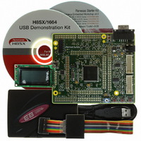
CPU Board, LCD Display Module, E8 Emulator, Cable, QuickStart Guide and CD-ROM
For Use With/related Products
H8S/1664F
Lead Free Status / RoHS Status
Not applicable / Not applicable


All of the Flash ROM on the device (i.e. both MATs) can be programmed when the device is in Boot mode. Once in boot mode, the
boot-loader program pre-programmed into the microcontroller executes and attempts a connection with a host (for example a PC). On
establishing a connection with the microcontroller, the host may then transmit program data to the microcontroller via the appropriate
programming port.
Table 8-1 below shows the programming port for this Renesas Microcontroller and its associated pins
This device supports an E8 debugging interface. The E8 provides additional debugging features including hardware breakpoints and
hardware trace capability. (Check with the website at
Connect the E8 to port J6.
To enable the E8 functions the user must ensure that the jumper link in position J15 is removed.
This device supports an optional E10A debugging interface. The E10A provides additional debugging features including hardware
breakpoints and hardware trace capability. (Check with the website at
To utilise the E10A the user will need to fit a 14 way boxed header to J5. To enable the E10A functions the user should also fit a jumper link
in position J15.
When J15 is fitted the microcontroller will not operate correctly unless operated via the E10A.
The microcontroller must enter boot mode for programming, and the programming port must be connected to a host for program download.
To execute the boot transition, and allow programs to download to the microcontroller, the user must perform the following procedure:
Ensure jumper link in position J16 and R133 are not fitted. (Default position)
Press the BOOT switch and keep this held down.
Press the RESET switch once, and release.
Release the BOOT switch The BOOT LED will be illuminated.
Now connect a USB cable between the host PC and the RSK at J12.
8.1.E8 Header
8.2.E10A Header
8.3.USB port programming
E8 Port (J6)
CPU board Signal Name
Programming Port Table – Programming port pins and their CPU board signal names
Chapter 8.Programming Methods
Table 8-1: Serial Port Boot Channel
E8_TXD, PIN 5
PTTX (Port 6, Pin0)
www.renesas.com
21
www.renesas.com
or your distributor for a full feature list).
E8_RXD, PIN 11
PTRX (Port 6, Pin 1)
or your distributor for a full feature list).
Related parts for R0K561664S000BE
Image
Part Number
Description
Manufacturer
Datasheet
Request
R

Part Number:
Description:
KIT STARTER FOR M16C/29
Manufacturer:
Renesas Electronics America
Datasheet:

Part Number:
Description:
KIT STARTER FOR R8C/2D
Manufacturer:
Renesas Electronics America
Datasheet:

Part Number:
Description:
R0K33062P STARTER KIT
Manufacturer:
Renesas Electronics America
Datasheet:

Part Number:
Description:
KIT STARTER FOR R8C/23 E8A
Manufacturer:
Renesas Electronics America
Datasheet:

Part Number:
Description:
KIT STARTER FOR R8C/25
Manufacturer:
Renesas Electronics America
Datasheet:

Part Number:
Description:
KIT STARTER H8S2456 SHARPE DSPLY
Manufacturer:
Renesas Electronics America
Datasheet:

Part Number:
Description:
KIT STARTER FOR R8C38C
Manufacturer:
Renesas Electronics America
Datasheet:

Part Number:
Description:
KIT STARTER FOR R8C35C
Manufacturer:
Renesas Electronics America
Datasheet:

Part Number:
Description:
KIT STARTER FOR R8CL3AC+LCD APPS
Manufacturer:
Renesas Electronics America
Datasheet:
Part Number:
Description:
KIT STARTER FOR RX610
Manufacturer:
Renesas Electronics America
Datasheet:

Part Number:
Description:
KIT STARTER FOR R32C/118
Manufacturer:
Renesas Electronics America
Datasheet:

Part Number:
Description:
KIT DEV RSK-R8C/26-29
Manufacturer:
Renesas Electronics America
Datasheet:

Part Number:
Description:
KIT STARTER FOR SH7124
Manufacturer:
Renesas Electronics America
Datasheet:

Part Number:
Description:
KIT STARTER FOR H8SX/1622
Manufacturer:
Renesas Electronics America
Datasheet:

Part Number:
Description:
KIT DEV FOR SH7203
Manufacturer:
Renesas Electronics America
Datasheet: