EVB51JM128 Freescale Semiconductor, EVB51JM128 Datasheet - Page 2
EVB51JM128
Manufacturer Part Number
EVB51JM128
Description
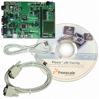
BOARD EVAL FOR MCF51JM128 MCU
Manufacturer
Freescale Semiconductor
Series
ColdFire®r
Type
MCUr
Datasheets
1.EVB51JM128.pdf
(23 pages)
2.EVB51JM128.pdf
(2 pages)
3.EVB51JM128.pdf
(3 pages)
4.EVB51JM128.pdf
(4 pages)
Specifications of EVB51JM128
Contents
Evaluation Board
Silicon Manufacturer
Freescale
Core Architecture
Coldfire
Core Sub-architecture
Coldfire V1
Silicon Core Number
MCF51J
Silicon Family Name
Flexis - MCF51JM
Rohs Compliant
Yes
For Use With/related Products
MCF51JM128
Lead Free Status / RoHS Status
Lead free / RoHS Compliant


About EVB51JM128 Labs
EVB51JM128 is a cost-effective kit that enables quick evaluation of the MCF51JM128 microcontroller.
These labs will show you the various USB examples included with the complimentary USB-LITE by
CMX stack for MCF51JM128. Start each lab with the board powered ON and both provided USB
cables connected between host PC and board.
mouse example.
1. Open CodeWarrior for Microcontrollers. From
2. From CodeWarrior startup dialog, click on “Start Using
3. Open the HID demo example project by pressing “CTRL”
4. With board turned off and both cables (A to B, A to
5. Turn the PWRSW switch to the ON position.
2. Press and hold button labeled “PTG1” while you reset
3. Release button labeled “PTG1.”
4. Your computer will recognize the MCF51JM128
mouse example which is described by Lab 1 in this
document. The HID class generic device example
can be entered by following the steps listed below.
This example will use a virtual C++ graphical user
interface (GUI) to read data from and write data to
the MCF51JM128 over USB interface.
1. Make sure the HID class mouse example is running.
2. Press and hold button labeled “PTG2,” while you reset
3. Release button labeled “PTG2.”
4. Your computer will recognize the MCF51JM128 as
LAB
LAB
LAB
Windows start menu, you can locate it using
the “Programs>Freescale CodeWarrior>CW for
Microcontroller V6.x>CodeWarrior IDE.exe” path.
CodeWarrior.”
+ “O” keys simultaneously. Follow C:\CMXUSB_LITE_
V1\usb-peripheral\projects\CodeWarrior\mcf51xx\
hid-demo and select “hid-demo.mcp” and click “Open.”
mini-AB, and RS-232 serial communication cable)
attached between host and board.
The +5V and +3V LED will illuminate.
example is running.
the microcontroller by pressing on button labeled “RESET.”
as an HID keyboard device and begin installation
(no user interaction needed). When hardware
the microcontroller by pressing on button labeled “RESET.”
an HID generic device (a.k.a. HID led demo) and
begin installation (no user interaction needed). When
hardware installation is complete, the MCF51JM128
will now behave as a generic USB device.
1
2
3
HID Class Mouse
This lab will pick up with the HID class
HID Class Keyboard Device
1. Make sure that the HID class mouse
HID Class Generic Device
This lab will pick up with the HID class
6.
7. From Connection Manager menu, select “EVB51JM128
8. From Erase and Program Flash menu, click on “Yes” to
9.
10. Your computer will recognize the MCF51JM128 as
5. Click button labeled “PTG1” for Page Up key action.
6. Click button labeled “PTG2” for Page Down key action.
7. Click Caps Lock and/or Num Lock key on your
5. Open “hid-led-demo.exe” GUI on your computer by
6. Click on virtual LED1, LED2, LED3 and LED4 buttons
7. Press buttons labeled
8. When done, click “Exit”
with hid class demo example by clicking on “Debug”
button, launching debugger.
on USB1” port and click on “Connect (Reset).”
allow the debugger to mass erase the microcontroller’s
on-chip flash memory and program it with the new
application.
an HID mouse device and begin installation (no user
interaction needed). When hardware installation is
complete, the MCF51JM128 will control your mouse
cursor by moving it back and forth.
installation is complete, the MCF51JM128 will
now behave as a keyboard.
keyboard and a “PTE3” and “PTE2” LEDs will turn
on/off respectively.
double-clicking on the file within the C:\CMXUSB_
LITE_V1\usb-peripheral\pc-side\hid-led-demo\Debug
directory.
on computer GUI to turn on/off the LEDs tied to “PTF0,”
“PTF1,” “PTE2” and “PTE3” on board.
“PTG1” and “PTG2” on
board to turn on/off SW1
and SW2 indicators on
computer GUI.
button on GUI.
Change the target to “EVB Flash,” then compile
and program the MCF51JM128 microcontroller
Click on the “Start/Continue (F5)” button in the
debugger to run application. Close debugger.
Easy-to-use USB
CDC and UART. The CDC to/from UART example
will demonstrate how to transfer commands/data
between the CDC virtual COM port and true serial
COM port using two independent terminal windows.
1. Open CodeWarrior for Microcontrollers. From
2. From CodeWarrior startup dialog, click on “Start Using
3. Open the CDC terminal example project by pressing
4. With board turned off and both cables (A to B, A to
5. Turn the PWRSW switch to the ON position. The +5V
6.
7. From Connection Manager menu, select “EVB51JM128
8. From Erase and Program Flash menu, click on “Yes” to
9.
10. Your computer will recognize the MCF51JM128 as a CDC
11. Verify the assigned virtual COM port for your board in
12. Launch two Hyperterminal window utilities.
13. In terminal window 1, set port assigned to your board
14. Set baud rate to 9600 (8 Data bits, none Parity,
15. Open COM port.
16. Set port to COM1.
17. Set baud rate to 9600.
LAB
Windows start menu, you can locate it using
the “Programs>Freescale CodeWarrior>CW for
Microcontroller V6.x>CodeWarrior IDE.exe” path.
CodeWarrior”.
“CTRL” + “O” keys simultaneously. Follow C:\CMXUSB_
LITE_V1\usb-peripheral\projects\CodeWarrior\mcf51xx\
cdc-demo and select “cdc-demo.mcp” and click “Open.”
mini-AB, and RS-232 serial communication cable)
attached between host and board.
and +3V LED will illuminate.
by clicking on “Debug” button, launching debugger.
on USB1” port and click on “Connect (Reset).”
allow the debugger to mass erase the microcontroller’s
on-chip flash memory and program it with the new
application.
device and begin installation. Some interaction is needed
to provide the USB driver. When prompted by computer
choose to specify location and provide the “mcf51xx.inf”
driver located in C:\CMXUSB_LITE_V1\usb-peripheral\
src\mcf51xx\cdc-demo. When hardware installation is
complete, the MCF51JM128 will now be recognized as a
CDC device with an assigned virtual COM port.
the device manager under “Ports (COM & LTP).”
Hyperterminal can be found under Start>Programs>
Accessories>Communications.
per device manager.
1 Stop bit, none Flow control).
4
Then compile and program the MCF51JM128
microcontroller with CDC class terminal example
Click on the “Start/Continue (F5)” button in the
debugger to run application. Close debugger.
CDC to/from UART
This lab will create a bridge between
18. Click on “Open Serial Port” button.
19. Type “Hello World!!” or any other characters in CDC side
20. Close COM ports and terminal windows.
one USB mouse or USB keyboard following the
steps listed below.
1. Change the factory setting on board. Change VBSEL
2. Open CodeWarrior for Microcontrollers. From
3. From CodeWarrior startup dialog, click on
4. Open the Host-HID example project by pressing “CTRL”
5. With board turned off and both cables (A to B, RS-232
6. Turn the PWRSW switch to the ON position. The +5V
7.
8. From Connection Manager menu, select “EVB51JM128
9. From Erase and Program Flash menu, click on “Yes” to allow
10. Close debugger.
LAB
and see them appear on UART side. The same will work
in the opposite direction.
jumper to 1 & 2 (HOST mode), also connect PD_EN
jumpers 1 & 2 (DPPD) and 3 & 4 (DNPD).
Windows start menu, you can locate it using
the “Programs>Freescale CodeWarrior>CW for
Microcontroller V6.x>CodeWarrior IDE.exe” path.
“Start Using CodeWarrior.”
+ “O” keys simultaneously. Follow C:\CMXUSB_LITE_
V1\usb-host\projects\CodeWarrior-6.x\hid\ and select
“host-hid-demo.mcp” and click “Open.”
serial cable) attached between host and board.
program the MCF51JM128 microcontroller with host-
hid-demo example by clicking on “Debug” button,
launching debugger.
on USB1” port and click on “Connect (Reset).”
the debugger to mass erase the microcontroller’s on-chip
flash memory and program it with the new application.
5
and +3V LED will illuminate.
Change the target to “EVB Flash,” compile and
Host-HID Class
This lab will show how to connect with
11. Launch Hyperterminal window utilities.
12. In terminal window, set port to COM1.
13. Set baud rate to 9600.
14. Click on “Open Serial Port” button.
15. Reset board.
16. The below information will be shown on the
Host HID Demo
Waiting for device
17. Connect USB mouse or USB keyboard to USB “A”
18. Disconnect device from board when completed.
USB Thumb Disk following the steps listed below.
1. Change the factory setting on board. Change VBSEL
2. Open CodeWarrior for Microcontrollers. From
3. From CodeWarrior startup dialog, click on
4. Open the Host-HID example project by pressing “CTRL”
5. With board turned off and both cables (A to B, RS-232
6. Turn the PWRSW switch to the ON position. The +5V
7.
8. From Connection Manager menu, select “EVB51JM128
9. From Erase and Program Flash menu, click on “Yes” to allow
10. Close debugger.
11. Launch Hyperterminal window utilities. Hyperterminal can be
12. In terminal window, set port to COM1.
13. Set baud rate to 9600.
14. Click on “Open Serial Port” button.
15. Reset board.
16. The below information will be shown on the terminal window.
Host HID Demo
Waiting for device
17. Connect USB Disk to the USB “A” Port (J3 on the board).
18. Disconnect device from board when completed.
LAB
Hyperterminal can be found under Start>
Programs>Accessories>Communications.
terminal window.
Port (J3 on the board). In terminal you will see the
transmitted information from device to host.
jumper to 1 & 2 (HOST mode), also connect PD_EN
jumper 1 & 2 (DPPD) and 3 & 4 (DNPD).
Windows start menu, you can locate it using
the “Programs>Freescale CodeWarrior>CW for
Microcontroller V6.x>CodeWarrior IDE.exe” path.
“Start Using CodeWarrior.”
+ “O” keys simultaneously. Follow C:\CMXUSB_LITE_
V1\usb-host\projects\CodeWarrior-6.x\mass-storage\
and select “mass-storage-demo.mcp” and click “Open.”
serial cable) attached between host and board.
and +3V LED will illuminate.
with mass-storage example by clicking on “Debug”
button, launching debugger.
on USB1” port and click on “Connect (Reset).”
the debugger to mass erase the microcontroller’s on-chip
flash memory and program it with the new application.
found under Start>Programs>Accessories>Communications.
In terminal type “help” to see available commands.
6
Change the target to “EVB Flash,” then compile
and program the MCF51JM128 microcontroller
Host-mass-storage Class
This lab will show how to connect with one
EVB51JM128 Lab Tutorials
Related parts for EVB51JM128
Image
Part Number
Description
Manufacturer
Datasheet
Request
R

Part Number:
Description:
Manufacturer:
Freescale Semiconductor, Inc
Datasheet:
Part Number:
Description:
Manufacturer:
Freescale Semiconductor, Inc
Datasheet:
Part Number:
Description:
Manufacturer:
Freescale Semiconductor, Inc
Datasheet:
Part Number:
Description:
Manufacturer:
Freescale Semiconductor, Inc
Datasheet:
Part Number:
Description:
Manufacturer:
Freescale Semiconductor, Inc
Datasheet:
Part Number:
Description:
Manufacturer:
Freescale Semiconductor, Inc
Datasheet:
Part Number:
Description:
Manufacturer:
Freescale Semiconductor, Inc
Datasheet:
Part Number:
Description:
Manufacturer:
Freescale Semiconductor, Inc
Datasheet:
Part Number:
Description:
Manufacturer:
Freescale Semiconductor, Inc
Datasheet:
Part Number:
Description:
Manufacturer:
Freescale Semiconductor, Inc
Datasheet:
Part Number:
Description:
Manufacturer:
Freescale Semiconductor, Inc
Datasheet:
Part Number:
Description:
Manufacturer:
Freescale Semiconductor, Inc
Datasheet:
Part Number:
Description:
Manufacturer:
Freescale Semiconductor, Inc
Datasheet:
Part Number:
Description:
Manufacturer:
Freescale Semiconductor, Inc
Datasheet:
Part Number:
Description:
Manufacturer:
Freescale Semiconductor, Inc
Datasheet: