RCDK8C Renesas Electronics America, RCDK8C Datasheet - Page 11
RCDK8C
Manufacturer Part Number
RCDK8C
Description
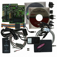
KIT DEV EVAL FOR CAN R8C/23
Manufacturer
Renesas Electronics America
Type
MCUr
Datasheet
1.RCDK8C.pdf
(29 pages)
Specifications of RCDK8C
Contents
2 Target Boards with CAN Transceiver, E8 Emulator, Cables and CD-ROM
For Use With/related Products
R8C/23
Lead Free Status / RoHS Status
Contains lead / RoHS non-compliant


6.1. Switches
There are four switches located on the board. The function of each switch and its connection are shown in Table 6-1.
*Refer to schematic for detailed connectivity information.
6.2. LEDs
There are six LEDs on the CPU board. The green ‘POWER’ LED lights when the board is powered. The orange ‘BOOT’ LED indicates the
device is in BOOT mode when lit. The four user LEDs are connected to an IO port and will light when their corresponding port pin is set low.
Table 6-2, below, shows the LED pin references and their corresponding microcontroller port pin connections.
6.3. Potentiometer
A single turn potentiometer is connected to AN8 (P1.0) of the microcontroller. This may be used to vary the input analog voltage value to
this pin between VREF and Ground.
RES
SW1/BOOT*
SW2*
SW3*
LED0
LED1
LED2
LED3
(As shown on silkscreen)
Switch
LED Reference
When pressed, the board microcontroller is reset.
Connects to an IRQ input for user controls.
The switch is also used in conjunction with the RES switch to place
the device in BOOT mode when not using the E8a debugger.
Connects to an IRQ input for user controls.
Connects to a Key In Interrupt input for user controls
Chapter 6. User Circuitry
Green
Orange
Red
Red
Colour
Table 6-1: Switch Functions
Function
Table 6-2: LED Port
Port 2.4
Port 2.5
Port 2.6
Port 2.7
Microcontroller Port Pin function
7
RESET Pin7
INT0 Pin25
(Port 4, pin 5)
INT1 Pin20
(Port 1, pin 7)
KI3 Pin24
(Port 1, pin 3)
Microcontroller
15
14
13
12
Microcontroller Pin
Number
Related parts for RCDK8C
Image
Part Number
Description
Manufacturer
Datasheet
Request
R

Part Number:
Description:
KIT STARTER FOR M16C/29
Manufacturer:
Renesas Electronics America
Datasheet:

Part Number:
Description:
KIT STARTER FOR R8C/2D
Manufacturer:
Renesas Electronics America
Datasheet:

Part Number:
Description:
R0K33062P STARTER KIT
Manufacturer:
Renesas Electronics America
Datasheet:

Part Number:
Description:
KIT STARTER FOR R8C/23 E8A
Manufacturer:
Renesas Electronics America
Datasheet:

Part Number:
Description:
KIT STARTER FOR R8C/25
Manufacturer:
Renesas Electronics America
Datasheet:

Part Number:
Description:
KIT STARTER H8S2456 SHARPE DSPLY
Manufacturer:
Renesas Electronics America
Datasheet:

Part Number:
Description:
KIT STARTER FOR R8C38C
Manufacturer:
Renesas Electronics America
Datasheet:

Part Number:
Description:
KIT STARTER FOR R8C35C
Manufacturer:
Renesas Electronics America
Datasheet:

Part Number:
Description:
KIT STARTER FOR R8CL3AC+LCD APPS
Manufacturer:
Renesas Electronics America
Datasheet:
Part Number:
Description:
KIT STARTER FOR RX610
Manufacturer:
Renesas Electronics America
Datasheet:

Part Number:
Description:
KIT STARTER FOR R32C/118
Manufacturer:
Renesas Electronics America
Datasheet:

Part Number:
Description:
KIT DEV RSK-R8C/26-29
Manufacturer:
Renesas Electronics America
Datasheet:

Part Number:
Description:
KIT STARTER FOR SH7124
Manufacturer:
Renesas Electronics America
Datasheet:

Part Number:
Description:
KIT STARTER FOR H8SX/1622
Manufacturer:
Renesas Electronics America
Datasheet:

Part Number:
Description:
KIT DEV FOR SH7203
Manufacturer:
Renesas Electronics America
Datasheet: