R0K561622S000BE Renesas Electronics America, R0K561622S000BE Datasheet - Page 21
R0K561622S000BE
Manufacturer Part Number
R0K561622S000BE
Description
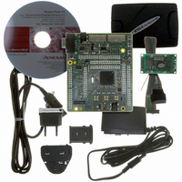
KIT STARTER FOR H8SX/1622
Manufacturer
Renesas Electronics America
Series
Renesas Starter Kits (RSK)r
Type
MCUr
Specifications of R0K561622S000BE
Contents
Board, Cables, CD, Debugger, Power Supply
Silicon Manufacturer
Renesas
Features
Coding And Debugging, E10A Emulator, RS232 Serial Connection
Kit Contents
Board
Silicon Family Name
H8SX/1622F
Silicon Core Number
R5F61622N50LGV
Lead Free Status / RoHS Status
Lead free / RoHS Compliant
For Use With/related Products
H8SX/1622
Lead Free Status / RoHS Status
Lead free / RoHS Compliant, Lead free / RoHS Compliant


This RSK supports Boot mode, User mode, MCU Extension Mode (ROM Active) and Single Chip mode.
Details of programming the FLASH memory is described in the H8SX/1622 Group Hardware Manual.
7.1. Boot mode
The boot mode settings for this RSK are shown in Table 7-1: Boot Mode pin settings below:
The software supplied with this RSK supports debugging with E10A which does not need Boot mode. To enter the Boot manually, do not
connect the E10A. Press and hold the SW1/BOOT. The BOOT LED will be illuminated to indicate that the microcontroller is in boot mode.
7.2. User mode
Refer to H8SX/1622 Group Hardware Manual for details of User mode. The user mode settings for this RSK are shown in Table 7-2: user
Mode pin settings below:
7.3. MCU Extension mode (ROM Active)
Refer to H8SX/1622 Group Hardware Manual for details of Extended mode. The MCU Extension mode settings for this RSK are shown in
Table 7-3: MCU Extension Mode pin setting
7.4. Single chip mode
This is the default operating mode of this RSK. Refer to H8SX/1622 Group Hardware Manual for details of Single chip mode. The Single
chip mode settings for this RSK are shown in Table 7-4:
T
EMLE
EMLE
EMLE
EMLE
0
0
0
0
MD2
MD2
MD2
MD2
Table 7-3: MCU Extension Mode (ROM Active) pin settings
0
0
1
1
s below:
Chapter 7. Modes
Table 7-4: Single chip Mode pin settings
T
Table 7-1: Boot Mode pin settings
Table 7-2: User Mode pin settings
MD1
MD1
MD1
MD1
1
0
1
1
Single chip mode pin settings below:
19
MD0
MD0
MD0
MD0
0
1
0
1
LSI State after Reset End
Boot Mode
LSI State after Reset End
User Mode
LSI State after Reset End
MCU Extension Mode (ROM Active)
LSI State after Reset End
Single chip Mode
Related parts for R0K561622S000BE
Image
Part Number
Description
Manufacturer
Datasheet
Request
R

Part Number:
Description:
KIT STARTER FOR M16C/29
Manufacturer:
Renesas Electronics America
Datasheet:

Part Number:
Description:
KIT STARTER FOR R8C/2D
Manufacturer:
Renesas Electronics America
Datasheet:

Part Number:
Description:
R0K33062P STARTER KIT
Manufacturer:
Renesas Electronics America
Datasheet:

Part Number:
Description:
KIT STARTER FOR R8C/23 E8A
Manufacturer:
Renesas Electronics America
Datasheet:

Part Number:
Description:
KIT STARTER FOR R8C/25
Manufacturer:
Renesas Electronics America
Datasheet:

Part Number:
Description:
KIT STARTER H8S2456 SHARPE DSPLY
Manufacturer:
Renesas Electronics America
Datasheet:

Part Number:
Description:
KIT STARTER FOR R8C38C
Manufacturer:
Renesas Electronics America
Datasheet:

Part Number:
Description:
KIT STARTER FOR R8C35C
Manufacturer:
Renesas Electronics America
Datasheet:

Part Number:
Description:
KIT STARTER FOR R8CL3AC+LCD APPS
Manufacturer:
Renesas Electronics America
Datasheet:
Part Number:
Description:
KIT STARTER FOR RX610
Manufacturer:
Renesas Electronics America
Datasheet:

Part Number:
Description:
KIT STARTER FOR R32C/118
Manufacturer:
Renesas Electronics America
Datasheet:

Part Number:
Description:
KIT DEV RSK-R8C/26-29
Manufacturer:
Renesas Electronics America
Datasheet:

Part Number:
Description:
KIT STARTER FOR SH7124
Manufacturer:
Renesas Electronics America
Datasheet:

Part Number:
Description:
KIT DEV FOR SH7203
Manufacturer:
Renesas Electronics America
Datasheet:
Part Number:
Description:
KIT STARTER FOR R8C/18191A1B
Manufacturer:
Renesas Electronics America
Datasheet: