DM163035 Microchip Technology, DM163035 Datasheet - Page 51
DM163035
Manufacturer Part Number
DM163035
Description
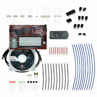
KIT DEVELOPMENT PICDEM LAB
Manufacturer
Microchip Technology
Type
MCUr
Datasheet
1.DM163035.pdf
(96 pages)
Specifications of DM163035
Contents
Board, Cable, Components, CD, PICkit Programmer
Processor To Be Evaluated
PIC10F, PIC12F615, PIC16F616
Data Bus Width
8 bit
Operating Supply Voltage
1.3 V to 5 V
Silicon Manufacturer
Microchip
Core Architecture
PIC
Core Sub-architecture
PIC10, PIC12, PIC16
Silicon Core Number
PIC10F, PIC12F, PIC16F
Silicon Family Name
PIC10F2xx, PIC12F6xx, PIC16F6xx
Lead Free Status / RoHS Status
Lead free / RoHS Compliant
For Use With/related Products
PIC10F206, PIC16F690, PIC16F819
Lead Free Status / Rohs Status
Lead free / RoHS Compliant


© 2009 Microchip Technology Inc.
5. The Do_Outputs() code from the previous lab stays the same.
6. Copy/paste the code in Example 3-21 into the Timing() over the code from the
EXAMPLE 3-21:
7. Copy/paste the code in Example 3-22 over the main() code from the previous
EXAMPLE 3-22:
8. Compile the project, there should be no errors.
3.4.4.4
Program the PIC16F690. Once programmed, the LEDs connected to PORTC should
sequentially light from left-to-right in 10 mS intervals. When the push button is pressed,
the LEDs should change directions and sequentially light from right-to-left.
Continuously pressing the push button will change the direction each time.
It should be noted that the push button press inconsistently changes the direction of
sequential flashing. The problem here is that the firmware performs a technique called
"Polling" to check the state of the RA0 pin that connects to the push button. Therefore,
the state of RA0 is checked only once each time through the software control loop when
the Get_Inputs() is called. This polling is subject to the timing of the software con-
trol loop and will lead to push button presses being missed. If the Timing() remained
at the 1 second delay as implemented in the previous lab, this would have made
matters worse. The next labs will remedy these issues through the use of interrupts.
The solution for this project is located in the
C:\PICDEM_Lab\GPIO_Labs\GPIO_Lab5\solution directory.
Note:
previous lab.
lab.
unsigned int delay_var = 9997;
//Keep looping until the delay_var is
// equal to zero (should take 10mS)
while(--delay_var);
Initialize(); //Initialize the relevant registers
while(1)
{
}
TESTING THE APPLICATION
This lab now utilizes a 10 mS delay to time the software control loop.
Get_Inputs();//Evaluate inputs
Decide();//Make any decisions
Do_Outputs(); //Perform any outputs
Timing();//Sets execution rate of the
General Purpose Input/Output Labs
TIMING() CODE FOR GPIO LAB 5
MAIN() CODE FOR LAB 5
//Software Control Loop
DS41369A-page 47
Related parts for DM163035
Image
Part Number
Description
Manufacturer
Datasheet
Request
R

Part Number:
Description:
Manufacturer:
Microchip Technology Inc.
Datasheet:
Part Number:
Description:
Manufacturer:
Microchip Technology Inc.
Datasheet:
Part Number:
Description:
Manufacturer:
Microchip Technology Inc.
Datasheet:
Part Number:
Description:
Manufacturer:
Microchip Technology Inc.
Datasheet:
Part Number:
Description:
Manufacturer:
Microchip Technology Inc.
Datasheet:
Part Number:
Description:
Manufacturer:
Microchip Technology Inc.
Datasheet:
Part Number:
Description:
Manufacturer:
Microchip Technology Inc.
Datasheet:
Part Number:
Description:
Manufacturer:
Microchip Technology Inc.
Datasheet: