DM163035 Microchip Technology, DM163035 Datasheet - Page 72
DM163035
Manufacturer Part Number
DM163035
Description
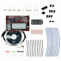
KIT DEVELOPMENT PICDEM LAB
Manufacturer
Microchip Technology
Type
MCUr
Datasheet
1.DM163035.pdf
(96 pages)
Specifications of DM163035
Contents
Board, Cable, Components, CD, PICkit Programmer
Processor To Be Evaluated
PIC10F, PIC12F615, PIC16F616
Data Bus Width
8 bit
Operating Supply Voltage
1.3 V to 5 V
Silicon Manufacturer
Microchip
Core Architecture
PIC
Core Sub-architecture
PIC10, PIC12, PIC16
Silicon Core Number
PIC10F, PIC12F, PIC16F
Silicon Family Name
PIC10F2xx, PIC12F6xx, PIC16F6xx
Lead Free Status / RoHS Status
Lead free / RoHS Compliant
For Use With/related Products
PIC10F206, PIC16F690, PIC16F819
Lead Free Status / Rohs Status
Lead free / RoHS Compliant


PICDEM
DS41369A-page 68
TM
4.2.6
4.2.6.1
To configure the peripherals used in this lab, the following registers are used:
1. Timer1 Control Register: T1CON (Register 6-1 in Section 6 of the PIC16F690
4.2.6.2
This lab expands on concepts discussed in the previous comparator lab by
implementing intelligence to create a higher resolution temperature sensor
measurement application. The comparator will be configured to operate as a simple
relaxation oscillator with the addition of a few external components. The internal
voltage reference will still be used to provide the non-inverting reference only this time
the 0.6V fixed voltage reference feature will be implemented.
The basic oscillator circuit is shown in Figure 4-4.
FIGURE 4-4:
Referring to Figure 4-4, at start-up, the capacitor connected to the inverting reference
of Comparator 1 is completely discharged. Therefore, the voltage present on the invert-
ing reference is 0V which is less than the 0.6V fixed voltage reference on the
non-inverting reference and Comparator 1’s output goes high. This rapidly charges the
capacitor through the diode (D1) to a level approximately equal to V
parator detects that the inverting reference input is greater than the 0.6V fixed voltage
reference, the output transitions low. The charge across the capacitor then discharges
slowly across the resistor R1. Once the capacitor charge drops below the 0.6V fixed
Lab Development Board User’s Guide
- This register is used to control Timer1 and select various features of the
data sheet)
module. In this lab the register will be used to enable Timer1 and select the
clock source.
V
Lab 3: Higher Resolution Sensor Readings Using a Single
Comparator
NEW REGISTERS USED IN THIS LAB
OVERVIEW
t
BASIC RELAXATION OSCILLATOR CIRCUIT
R
1
C12IN0-
V
SS
PIC16F690
V
0.6V
SS
C
1
+
_
C1OUT
© 2009 Microchip Technology Inc.
D1
V
DD
. Once the Com-
t
Related parts for DM163035
Image
Part Number
Description
Manufacturer
Datasheet
Request
R

Part Number:
Description:
Manufacturer:
Microchip Technology Inc.
Datasheet:
Part Number:
Description:
Manufacturer:
Microchip Technology Inc.
Datasheet:
Part Number:
Description:
Manufacturer:
Microchip Technology Inc.
Datasheet:
Part Number:
Description:
Manufacturer:
Microchip Technology Inc.
Datasheet:
Part Number:
Description:
Manufacturer:
Microchip Technology Inc.
Datasheet:
Part Number:
Description:
Manufacturer:
Microchip Technology Inc.
Datasheet:
Part Number:
Description:
Manufacturer:
Microchip Technology Inc.
Datasheet:
Part Number:
Description:
Manufacturer:
Microchip Technology Inc.
Datasheet: