AT91SAM7A1-EK Atmel, AT91SAM7A1-EK Datasheet - Page 15
AT91SAM7A1-EK
Manufacturer Part Number
AT91SAM7A1-EK
Description
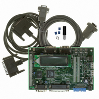
BOARD EVAL FOR AT91SAM7A1
Manufacturer
Atmel
Series
AT91SAM Smart ARMr
Type
MCUr
Datasheet
1.AT91SAM7A1-EK.pdf
(31 pages)
Specifications of AT91SAM7A1-EK
Contents
Evaluation Board, Parallel Cable and CD-ROM
Processor To Be Evaluated
AT91SAM7A1
Data Bus Width
32 bit
Interface Type
RS-232
For Use With/related Products
AT91SAM7A1
Lead Free Status / RoHS Status
Contains lead / RoHS non-compliant
Available stocks
Company
Part Number
Manufacturer
Quantity
Price
Company:

Part Number:
AT91SAM7A1-EK
Manufacturer:
Atmel
Quantity:
2


3.7
3.8
AT91SAM7A1-EK Evaluation Board User Guide
Crystal
Oscillators and
Clock
Distribution
Memory
Organization
Note:
The LIN interfaces are connected to two three-pin header connectors:
The pinout for the connector J19 used by the USART1 is described Table 3-8.
Table 3-8. J19 Pinout
Note:
The pin-out for the connector J4 used by the USART0 is described Table 3-9.
Table 3-9. J4 Pinout
Note:
Figure 3-2. Male DB9 Connector
For more details, refer to Figure 4-6.
The system clock is derived from a 6 MHz crystal oscillator mounted on-board. At reset,
the on-chip PLL-based frequency multiplier is disabled, using the frequency of the crys-
tal oscillator as the default master clock. The low-frequency clock used for the low-
power mode, the Watchtimer module and the Watchdog module can be leaded by a 32
kHz crystal oscillator or a division of the 6 MHz crystal oscillator. At reset, the low-fre-
quency clock is configured on the 32 kHz crystal oscillator mounted on-board.
For more details, refer to Figure 4-2.
The Flash memory is an AT49BV1614A (1Mx16-bit). Write-protection for half of the on-
board Flash memory is provided. Output 2 of Jumper J15 drives the address pin 20 of
the Flash.
To access the whole memory, put a jumper in J5: 1 - 2.
Connector J19
Connector J4
Depending on the strap configuration, either SubD9 pin 1 or 4 can be controlled
by UPIO or by USART0 pins.
The schematic of these connectors is the same as the one used by the CAN0
module (see Section 3.5).
1. Depends on the strap configuration.
1. Depends on the strap configuration.
J19 Pin
J4 Pin
1
2
3
1
2
3
LIN (Local Interconnect Network)
LIN (Local Interconnect Network)
1
6
Vs (8V - 18V)
Vs (8V - 18V)
2
Function
Function
Ground
7
Ground
3
8
4
9
5
AT91SAM7A1 Pin
AT91SAM7A1 Pin
TXD1/RXD1
TXD0/RXD0
6114A–ATARM–09/04
GND
GND
(1)
(1)
3-5
Related parts for AT91SAM7A1-EK
Image
Part Number
Description
Manufacturer
Datasheet
Request
R

Part Number:
Description:
MCU ARM9 64K SRAM 144-LFBGA
Manufacturer:
Atmel
Datasheet:

Part Number:
Description:
IC ARM7 MCU FLASH 256K 100LQFP
Manufacturer:
Atmel
Datasheet:

Part Number:
Description:
IC ARM9 MPU 217-LFBGA
Manufacturer:
Atmel
Datasheet:
Part Number:
Description:
MCU ARM9 ULTRA LOW PWR 217-LFBGA
Manufacturer:
Atmel
Datasheet:

Part Number:
Description:
MCU ARM9 324-TFBGA
Manufacturer:
Atmel
Datasheet:
Part Number:
Description:
IC MCU ARM9 SAMPLING 217CBGA
Manufacturer:
Atmel
Datasheet:
Part Number:
Description:
IC ARM9 MCU 217-LFBGA
Manufacturer:
Atmel
Datasheet:

Part Number:
Description:
IC ARM9 MCU 208-PQFP
Manufacturer:
Atmel
Datasheet:
Part Number:
Description:
MCU ARM 512K HS FLASH 100-LQFP
Manufacturer:
Atmel
Datasheet:

Part Number:
Description:
MCU ARM 512K HS FLASH 100-TFBGA
Manufacturer:
Atmel
Datasheet:
Part Number:
Description:
IC ARM9 MCU 200 MHZ 324-TFBGA
Manufacturer:
Atmel
Datasheet:

Part Number:
Description:
IC ARM MCU 16BIT 128K 256BGA
Manufacturer:
Atmel
Datasheet:

Part Number:
Description:
IC ARM7 MCU 32BIT 128K 64LQFP
Manufacturer:
Atmel
Datasheet:

Part Number:
Description:
IC ARM7 MCU FLASH 256K 128-LQFP
Manufacturer:
Atmel
Datasheet:
Part Number:
Description:
IC ARM7 MCU FLASH 512K 128-LQFP
Manufacturer:
Atmel
Datasheet: