DEMO9RS08LA8 Freescale Semiconductor, DEMO9RS08LA8 Datasheet - Page 7
DEMO9RS08LA8
Manufacturer Part Number
DEMO9RS08LA8
Description
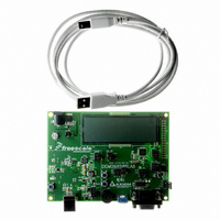
BOARD DEMO FOR MC9RSOLA8 MCU
Manufacturer
Freescale Semiconductor
Series
RS08r
Type
MCUr
Datasheets
1.DEMO9RS08LA8.pdf
(14 pages)
2.DEMO9RS08LA8.pdf
(8 pages)
3.DEMO9RS08LA8.pdf
(34 pages)
4.DEMO9RS08LA8.pdf
(2 pages)
Specifications of DEMO9RS08LA8
Contents
Board, Cable, DVD
Silicon Manufacturer
Freescale
Core Architecture
RS08
Core Sub-architecture
RS08
Silicon Core Number
MC9RS08
Silicon Family Name
RS08LA
Kit Contents
Board Cables CD Docs
Rohs Compliant
Yes
For Use With/related Products
MC9RS08LA8
Lead Free Status / RoHS Status
Contains lead / RoHS non-compliant
Available stocks
Company
Part Number
Manufacturer
Quantity
Price
Company:

Part Number:
DEMO9RS08LA8
Manufacturer:
Freescale Semiconductor
Quantity:
135


U S E R
SOFTWARE DEVELOPMENT
Software development requires the use of a compiler or an assembler supporting the HCS08
instruction set and a host PC operating a debug interface. CodeWarrior Development Studio
for Microcontrollers is supplied with this board for application development and debug.
DEVELOPMENT SUPPORT
Application development and debug for the target MC9RSO8LA8 is supported through the
background debug mode (BDM) interface. The BDM interface consists of an integrated USB-
Multilink BDM and a 6-pin interface header (BDM_PORT). The BDM_PORT header allows
connecting a HCS12/HCS08 BDM cable.
Integrated BDM
The DEMO9RSO8LA8 board features an integrated USB-Multilink BDM from P&E
Microcomputer Systems. The integrated USB-Multilink BDM supports application development
and debugging via background debug mode.
integrated USB-Multilink BDM. A USB, type B, connector provides connection from the target
board to the host PC.
The integrated USB-Multilink BDM provides power and ground to target board eliminating the
need to power the board externally. Power from the USB-Multilink BDM is derived from the
USB bus; therefore, total current consumption for the target board, and connected circuitry,
must not exceed 500mA. This current limit describes the current supplied by the USB cable
to the BDM circuit, the target board, and any connected circuitry. Excessive current drain will
violate the USB specification causing the bus to disconnect. Damage to the host PC USB hub
or the target board may result.
BDM OPTION Headers
Option headers at JP1400 and JP401 connect the integrated BDM to the target board. Option
header JP1 connects signals RST* and BGND to the target MCU.
Figure 1: JP400 Option Header
Option header JP2 connects two timer channels to the BDM to facilitate the Signal Analyzer
functionality.
G U I D E
• • RST*
• • BGND
Connects BDM RESET* to target MCU
Connects BDM BGND to target MCU
7
All necessary signals are provided by the
Related parts for DEMO9RS08LA8
Image
Part Number
Description
Manufacturer
Datasheet
Request
R

Part Number:
Description:
Manufacturer:
Freescale Semiconductor, Inc
Datasheet:
Part Number:
Description:
Manufacturer:
Freescale Semiconductor, Inc
Datasheet:
Part Number:
Description:
Manufacturer:
Freescale Semiconductor, Inc
Datasheet:
Part Number:
Description:
Manufacturer:
Freescale Semiconductor, Inc
Datasheet:
Part Number:
Description:
Manufacturer:
Freescale Semiconductor, Inc
Datasheet:
Part Number:
Description:
Manufacturer:
Freescale Semiconductor, Inc
Datasheet:
Part Number:
Description:
Manufacturer:
Freescale Semiconductor, Inc
Datasheet:
Part Number:
Description:
Manufacturer:
Freescale Semiconductor, Inc
Datasheet:
Part Number:
Description:
Manufacturer:
Freescale Semiconductor, Inc
Datasheet:
Part Number:
Description:
Manufacturer:
Freescale Semiconductor, Inc
Datasheet:
Part Number:
Description:
Manufacturer:
Freescale Semiconductor, Inc
Datasheet:
Part Number:
Description:
Manufacturer:
Freescale Semiconductor, Inc
Datasheet:
Part Number:
Description:
Manufacturer:
Freescale Semiconductor, Inc
Datasheet:
Part Number:
Description:
Manufacturer:
Freescale Semiconductor, Inc
Datasheet:
Part Number:
Description:
Manufacturer:
Freescale Semiconductor, Inc
Datasheet: