DEMO9S08QB8 Freescale Semiconductor, DEMO9S08QB8 Datasheet - Page 35
DEMO9S08QB8
Manufacturer Part Number
DEMO9S08QB8
Description
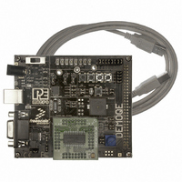
BOARD DEMO FOR 9S08 QB MCU
Manufacturer
Freescale Semiconductor
Type
MCUr
Specifications of DEMO9S08QB8
Contents
Board, Cable
Silicon Manufacturer
Freescale
Core Architecture
HCS08
Core Sub-architecture
HCS08
Silicon Core Number
MC9S08
Silicon Family Name
S08QB
Kit Contents
Board
Rohs Compliant
Yes
For Use With/related Products
MC9S08QB8
Lead Free Status / RoHS Status
Lead free / RoHS Compliant


7.5.3
7.5.4
7.6
DEMO9S08QB8 User Manual
Buzzer
J15 - Accelerometer Sleep Mode Select Jumper SLEEP (J15)
J16 - Accelerometer 3-axis Signals Connection Jumper ACC_EN
The DEMO9S08QB8 integrates a Piezo Transducer whose resonant
frequency is 4.0KHz. Jumper J19 connects to PTB5 to control this buzzer.
Figure 7-13: Accelerometer Sleep Mode Jumper settings (J15)
Figure 7-12: Accelerometer g-Select2 Jumper settings (J14)
Figure 7-14: Accelerometer Signal Output ACC_EN (J16)
Enables the 3-axis accelerometer. This is the default setting.
Puts the 3-axis accelerometer into sleep mode. The user may control
PTC4 in firmware to enable or disable the accelerometer. In this
configuration, the user needs to pay close attention to LED PTC4 and
RSTO configuration.
The accelerometer output signals are jumper settable to PTA7, PTA6,
PTC7, and PTA1. PTA6 and PTC7 share the same Y-axis signal. By
default, the Y-axis signal is connected to PTA6.
31
Related parts for DEMO9S08QB8
Image
Part Number
Description
Manufacturer
Datasheet
Request
R

Part Number:
Description:
Manufacturer:
STMicroelectronics
Datasheet:

Part Number:
Description:
DEMO BOARD FOR HMC6042/HMC1041Z
Manufacturer:
Honeywell Microelectronics & Precision Sensors

Part Number:
Description:
DEMO BOARD FOR HMC1042L/HMC1041Z
Manufacturer:
Honeywell Microelectronics & Precision Sensors
Datasheet:

Part Number:
Description:
KIT DEMO 4 SENSOR CHAN RS232
Manufacturer:
VTI Technologies
Datasheet:


Part Number:
Description:
DEMO: DC Power Supply, 32 Volts, 3 Amps
Manufacturer:
Tektronix
Part Number:
Description:
DEMO: Programmable DC Power Supply, 32 Volts, 3 Amps
Manufacturer:
Tektronix

Part Number:
Description:
Manufacturer:
Freescale Semiconductor, Inc
Datasheet:
Part Number:
Description:
Manufacturer:
Freescale Semiconductor, Inc
Datasheet:
Part Number:
Description:
Manufacturer:
Freescale Semiconductor, Inc
Datasheet:
Part Number:
Description:
Manufacturer:
Freescale Semiconductor, Inc
Datasheet:
Part Number:
Description:
Manufacturer:
Freescale Semiconductor, Inc
Datasheet:
Part Number:
Description:
Manufacturer:
Freescale Semiconductor, Inc
Datasheet:
Part Number:
Description:
Manufacturer:
Freescale Semiconductor, Inc
Datasheet:
Part Number:
Description:
Manufacturer:
Freescale Semiconductor, Inc
Datasheet: