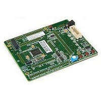
R0K33062PS001BE Renesas Electronics America, R0K33062PS001BE Datasheet - Page 4

R0K33062PS001BE
Manufacturer Part Number
R0K33062PS001BE
Description
R0K33062P STARTER KIT
Manufacturer
Renesas Electronics America
Series
Renesas Starter Kits (RSK)r
Type
MCUr
Specifications of R0K33062PS001BE
Contents
CPU Board, LCD Display Module, E8 Emulator, Cable, QuickStart Guide and CD-ROM
Silicon Manufacturer
Renesas
Features
Coding And Debugging, E8A Emulator, RS232 Serial Connection
Kit Contents
Board
Silicon Family Name
M16C/62P
Silicon Core Number
M30626FJPGP
Lead Free Status / RoHS Status
Lead free / RoHS Compliant
For Use With/related Products
M16C/62P
Lead Free Status / Rohs Status
Compliant
Other names
Q4300694
3. HEW Workspace
HEW integrates various tools such as compiler, assembler, debugger and editor into a common graphical user interface. To learn more on how to use HEW, open the
HEW manual installed on your computer (Start Menu > All Programs > Renesas > High-performance Embedded Workshop > Manual Navigator).
18. Launch HEW from the Start Menu. (Start Menu > All Programs > Renesas > High-performance Embedded Workshop).
19. In the “Welcome” dialog box: Verify “Create New Workspace” is selected. Click <OK>
20. In the “New Project Workspace” dialog box: Set the “CPU Family” to “M16C”, and verify the “Tool chain” is set to “Renesas M16C Standard”. Select
21. Enter a name for the workspace. The project name will be automatically completed with the Workspace name. You can change this name to ‘Tutorial’ if required.
22. On the “E8A_RSKM16C62P– Step 1” window: Select “Tutorial” and click <Next>.
23. On the “E8A_RSKM16C62P– Step 2” window: Click <Finish>.
24. On the Project Generator Information window: Click <OK>.
25. Select the Debug build configuration in the
26. Click on the ‘Build’ icon to compile, assemble and link the project.
4. Programming and Debug
27. Ensure the “SessionM16C_E8a_SYSTEM”
28. Click the <Connect> button on the debug toolbar
29. The “Emulator Mode” wizard will be shown.
30. Select “Erase Flash and Connect”.
31. Click <Next>
32. In the “Firmware Location” view, select “FF000” for the Program location and “7F00”
33. The “MCU Setting” view will be shown.
34. Set “PM13 (b3 of 000005H) is 1” checkbox.
35. Clear “PM10 (b0 of 000005H) is 1” checkbox.
36. Click <Finish>.
The project that is created has two configurations. The Release configuration can be used for the final release code version. The Debug configuration allows
modifications to the configuration for debugging.
“E8A_RSKM16C62P” from the left hand pane.
Click <OK>.
left hand drop down list on the tool bar.
session in the right hand drop down list on
the tool bar is selected.
Select the correct MCU group (M16C/62P) and device type (M30626FJP for
RSKM16C62P )
Please note that the “Emulator mode” view shown here will only appear the
FIRST time you connect to the target within a project. On subsequent
connections the “Emulator setting” dialog will appear, please choose the same
options to connect – refer to the RSKM16C62P Tutorial manual for details.
If the E8a is to provide power to the CPU board, select “Power Target from E8” and
choose the “5.0V” option. Otherwise connect a 5V centre positive supply.
for the Work RAM location, Clear the “Debugging of program that uses WDT”
checkbox; click <Next>.
Select the processor mode “Single-Chip Mode”. Ignore “Memory Space Expansion”.
Note: The first time the E8a is connected, you may be asked to choose a driver, select “Renesas Communications”, after a few seconds the “Interface”
and “Channel” numbers will be automatically displayed, click <Close> on the dialog.
D006344_11_S01_V04


