M52259EVB Freescale Semiconductor, M52259EVB Datasheet - Page 27
M52259EVB
Manufacturer Part Number
M52259EVB
Description
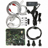
BOARD EVAL FOR 52259 COLDFIRE V2
Manufacturer
Freescale Semiconductor
Series
ColdFire®r
Type
MCUr
Datasheet
1.M52259EVB.pdf
(46 pages)
Specifications of M52259EVB
Contents
Board, Cables, Documentation, DVD, Flash Drive and Power Supply
Processor To Be Evaluated
MCF52259
Data Bus Width
32 bit
Interface Type
RS-232, Ethernet, USB
Silicon Manufacturer
Freescale
Core Architecture
Coldfire
Core Sub-architecture
Coldfire V2
Silicon Core Number
MCF52
Silicon Family Name
MCF5225x
Peak Reflow Compatible (260 C)
Yes
Rohs Compliant
Yes
For Use With/related Products
MCF52259
Lead Free Status / RoHS Status
Lead free / RoHS Compliant


Electrical Characteristics
27
1
2
3
4
5
6
7
8
9
10
11
12
13
14
15
recommends the use of
temperatures from exceeding the rated specification. System designers should be aware that device junction temperatures
can be significantly influenced by board layout and surrounding devices. Conformance to the device junction temperature
specification can be verified by physical measurement in the customer’s system using the
dissipation, and the method described in EIA/JESD Standard 51-2.
Per JEDEC JESD51-2 with the single-layer board (JESD51-3) horizontal.
Per JEDEC JESD51-6 with the board JESD51-7) horizontal.
Thermal resistance between the die and the printed circuit board in conformance with JEDEC JESD51-8. Board
temperature is measured on the top surface of the board near the package.
Thermal resistance between the die and the case top surface as measured by the cold plate method (MIL SPEC-883
Method 1012.1).
Thermal characterization parameter indicating the temperature difference between package top and the junction
temperature per JEDEC JESD51-2. When Greek letters are not available, the thermal characterization parameter is written
in conformance with Psi-JT.
recommends the use of
temperatures from exceeding the rated specification. System designers should be aware that device junction temperatures
can be significantly influenced by board layout and surrounding devices. Conformance to the device junction temperature
specification can be verified by physical measurement in the customer’s system using the
dissipation, and the method described in EIA/JESD Standard 51-2.
Per JEDEC JESD51-2 with the single-layer board (JESD51-3) horizontal.
Per JEDEC JESD51-6 with the board JESD51-7) horizontal.
100 LQFP
JA
JA
JA
and
and
and
jt
jt
jt
parameters are simulated in conformance with EIA/JESD Standard 51-2 for natural convection. Freescale
parameters are simulated in conformance with EIA/JESD Standard 51-2 for natural convection. Freescale
parameters are simulated in conformance with EIA/JESD Standard 51-2 for natural convection. Freescale
Junction to ambient, natural convection
Junction to ambient, natural convection
Junction to ambient, (@200 ft/min)
Junction to ambient, (@200 ft/min)
Junction to board
Junction to case
Junction to top of package
Maximum operating junction temperature
JA
JA
JA
and power dissipation specifications in the system design to prevent device junction
and power dissipation specifications in the system design to prevent device junction
and power dissipation specifications in the system design to prevent device junction
Table 8. Thermal Characteristics (continued)
MCF52259 ColdFire Microcontroller, Rev. 4
Characteristic
Single layer board (1s)
Four layer board (2s2p)
Single layer board (1s)
Four layer board (2s2p)
Natural convection
—
—
—
Symbol
JMA
JMA
T
JA
JA
JB
JC
jt
jt
jt
jt
j
parameter, the device power
parameter, the device power
parameter, the device power
Freescale Semiconductor
53
39
Value
42
33
25
105
9
2
13,14
1,15
17
18
1,3
1,3
16
C / W
C / W
C / W
C / W
C / W
C / W
C / W
Unit
o
C
Related parts for M52259EVB
Image
Part Number
Description
Manufacturer
Datasheet
Request
R

Part Number:
Description:
Manufacturer:
Freescale Semiconductor, Inc
Datasheet:
Part Number:
Description:
Manufacturer:
Freescale Semiconductor, Inc
Datasheet:
Part Number:
Description:
Manufacturer:
Freescale Semiconductor, Inc
Datasheet:
Part Number:
Description:
Manufacturer:
Freescale Semiconductor, Inc
Datasheet:
Part Number:
Description:
Manufacturer:
Freescale Semiconductor, Inc
Datasheet:
Part Number:
Description:
Manufacturer:
Freescale Semiconductor, Inc
Datasheet:
Part Number:
Description:
Manufacturer:
Freescale Semiconductor, Inc
Datasheet:
Part Number:
Description:
Manufacturer:
Freescale Semiconductor, Inc
Datasheet:
Part Number:
Description:
Manufacturer:
Freescale Semiconductor, Inc
Datasheet:
Part Number:
Description:
Manufacturer:
Freescale Semiconductor, Inc
Datasheet:
Part Number:
Description:
Manufacturer:
Freescale Semiconductor, Inc
Datasheet:
Part Number:
Description:
Manufacturer:
Freescale Semiconductor, Inc
Datasheet:
Part Number:
Description:
Manufacturer:
Freescale Semiconductor, Inc
Datasheet:
Part Number:
Description:
Manufacturer:
Freescale Semiconductor, Inc
Datasheet:
Part Number:
Description:
Manufacturer:
Freescale Semiconductor, Inc
Datasheet: