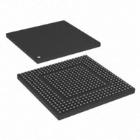
MPC8308-RDB Freescale Semiconductor, MPC8308-RDB Datasheet - Page 20

MPC8308-RDB
Manufacturer Part Number
MPC8308-RDB
Description
BOARD REF DESIGN MPC8308
Manufacturer
Freescale Semiconductor
Series
PowerQUICC II™ PROr
Type
MPUr
Datasheets
1.MPC8308VMAGD.pdf
(90 pages)
2.MPC8308VMAGD.pdf
(2 pages)
3.MPC8308-RDB.pdf
(36 pages)
4.MPC8308-RDB.pdf
(2 pages)
Specifications of MPC8308-RDB
Contents
Board, Cables, Documentation, Power Supply, Software
Ethernet Connection Type
Serial to Ethernet
Data Rate
10 Mbps, 100 Mbps, 1000 Mbps
Memory Type
DDR2, SDRAM
Interface Type
HSSI
Operating Voltage
1.5 V
Operating Current
5 uA
Maximum Power Dissipation
1000 mW
Operating Temperature Range
- 55 C to + 125 C
Product
Modules
For Use With/related Products
MPC8308
Lead Free Status / RoHS Status
Lead free / RoHS Compliant
Connectors, Jumpers, Switches, and LEDs
3.1
The COP connector allows the user to connect a COP/JTAG-based debugger to the MPC8308 for
debugging.
20
Reference
COP Connector (P2)
Table 5
D11
D12
D16
D17
D18
S1
S2
S3
S4
D1
D2
D3
D4
D5
D6
D7
J8
J1
J2
J4
J6
J7
Table 4. Connectors, Headers, Jumpers, Switches, and LEDs (continued)
lists the pin assignments of the COP connector.
SPI interfaces connector
MCU battery backup enable. Install jumper 1-2 to power MCU in battery standby mode. This
is required if the MCU is programmed to function as a real time clock. Install jumper 2-3
(default) to power real time clock chip DS1339 if the MCU real time clock function is not used
12V fan connector
RS-232C #2 select header. Selects RS-232C #2 on P1 (bottom) to be connected to either
CPU UART2 (Install jumpers 1–3, 2–4 as default) or MCU SCI (Install jumpers 3–5, 4–6).
Alternatively, CPU UART2 can be connected to the MCU SCI instead (Install jumpers 5–7,
6–8).
MCU LED1 header. Connection to external, MCU controlled LED1. Pin 1 is Anode
CPU Power-on reset source jumper. CPU Power-On Reset can be controlled by a hardware
MIC811 reset chip (jumper 2–3 as default) or by MCU firmware (jumper 1–2).
Board revision and boot Flash selection switch.
Reset configuration word source selection switch.
Power-on push button. Powers up the MPC8308_RDB board.
System reset button. Resets the MPC8308_RDB board.
USB PHY CTL0
USB PHY CTL1
USB VBUS
Enet1 LINK10
Enet1 LINK100
Enet1 DUPLEX
Enet1 RX
MCU LED1
MCU LED2
5 V Indicator
5 V standby indicator
3.3V Indicator
PowerQUICC™ MPC8308_RDB User’s Guide, Rev. 3
Switches
Jumpers
LEDs
Description
Micetek International Inc.


