EDK7145 Renesas Electronics America, EDK7145 Datasheet - Page 9
EDK7145
Manufacturer Part Number
EDK7145
Description
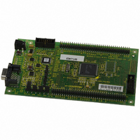
DEV EVALUATION KIT SH7145
Manufacturer
Renesas Electronics America
Type
MCUr
Datasheets
1.EDK7145.pdf
(19 pages)
2.EDK7145.pdf
(4 pages)
3.EDK7145.pdf
(5 pages)
4.EDK7145.pdf
(22 pages)
Specifications of EDK7145
Contents
2G (Second-generation) Evaluation Board, HEW debugger support, Cable and CD-ROM
Lead Free Status / RoHS Status
Contains lead / RoHS non-compliant
For Use With/related Products
SH7145
Lead Free Status / RoHS Status
Not Compliant, Contains lead / RoHS non-compliant


5.
The EDK has a number of configuration settings set by jumpers CJ4 (A, B, C, D), CJ5 (A, B, C, D) and zero-ohm links.
Common EDK functions can be set using the jumpers as described in sections 5.3 and 5.2. The additional zero-ohm links
provide additional features that may be required to interface with other systems.
All the Jumper link settings are three pin options. There are four sets of options on each header.
The headers are numbered from 1 to 12 with pin 1 marked on the PCB by an arrow pointing to the pin. The diagram below
shows the numbering of these jumper links and indicates jumpers fitted 1-2 for each three-pin jumper.
5.1. J
The following tables define each jumper and its settings.
5.2. U
CJ5 is used to set the operating mode of the microcontroller.
These jumpers must be fitted at all times to ensure correct operation of the EDK.
B
UMPER
SER
OARD
M
ODE
L
O
INKS
CJ 5-A
Default 2-3
CJ 5-B
Default 1-2
CJ 5-C
Default 1-2
CJ 5-D
Default 1-2
PTIONS
Jumper
S
ETTINGS
1 2
1
User Mode Setting Bit 0
User Mode Setting Bit 1
User Mode Setting Bit 2
User Mode Setting Bit 3
Jumper
– CJ5
1,2,3
A
2
Power
D-Type
T
RESET
9-Way
Switch
Switch
NMI
ABLE
3
BOOT LED
Power LED
User1 LED
User2 LED
3
Function
5-1: U
4
1
Jumper
1,2,3
B
5
2
BOOT
Switch
SER
Programming
6
3
F
M
FLASH
CJ5
CJ4
IGURE
ODE
7
1
Jumper
1,2,3
: J
5-1: J
C
8
UMPER
2
MD0 pulled High
MD1 pulled High
MD2 pulled High
MD3 pulled High
9
MD4
5V
3V3
UVcc
GND
RESn
FW
NMIn
ULED1
ULED2
PSCK
PTXD
PRXD
RX232
DTXD
DRXD
RXDISn
DCTS
DRTS
MD0
MD1
MD2
MD3
UPM
CSn
3
UMPER
S
10
J2
J1
ETTINGS
Setting 1-2
1
Jumper
1,2,3
C
11
D
ONFIGURATION
2
(D
12
3
EFAULT SETTINGS IN BOLD
Microprocessor
HITACHI
MD0 pulled Low
MD1 pulled Low
MD2 pulled Low
MD3 pulled Low
Setting 2-3
SRAM
74
xx
08
)
H-UDI
AUD/
E10A
9
Related parts for EDK7145
Image
Part Number
Description
Manufacturer
Datasheet
Request
R

Part Number:
Description:
KIT STARTER FOR M16C/29
Manufacturer:
Renesas Electronics America
Datasheet:

Part Number:
Description:
KIT STARTER FOR R8C/2D
Manufacturer:
Renesas Electronics America
Datasheet:

Part Number:
Description:
R0K33062P STARTER KIT
Manufacturer:
Renesas Electronics America
Datasheet:

Part Number:
Description:
KIT STARTER FOR R8C/23 E8A
Manufacturer:
Renesas Electronics America
Datasheet:

Part Number:
Description:
KIT STARTER FOR R8C/25
Manufacturer:
Renesas Electronics America
Datasheet:

Part Number:
Description:
KIT STARTER H8S2456 SHARPE DSPLY
Manufacturer:
Renesas Electronics America
Datasheet:

Part Number:
Description:
KIT STARTER FOR R8C38C
Manufacturer:
Renesas Electronics America
Datasheet:

Part Number:
Description:
KIT STARTER FOR R8C35C
Manufacturer:
Renesas Electronics America
Datasheet:

Part Number:
Description:
KIT STARTER FOR R8CL3AC+LCD APPS
Manufacturer:
Renesas Electronics America
Datasheet:
Part Number:
Description:
KIT STARTER FOR RX610
Manufacturer:
Renesas Electronics America
Datasheet:

Part Number:
Description:
KIT STARTER FOR R32C/118
Manufacturer:
Renesas Electronics America
Datasheet:

Part Number:
Description:
KIT DEV RSK-R8C/26-29
Manufacturer:
Renesas Electronics America
Datasheet:

Part Number:
Description:
KIT STARTER FOR SH7124
Manufacturer:
Renesas Electronics America
Datasheet:

Part Number:
Description:
KIT STARTER FOR H8SX/1622
Manufacturer:
Renesas Electronics America
Datasheet:

Part Number:
Description:
KIT DEV FOR SH7203
Manufacturer:
Renesas Electronics America
Datasheet: