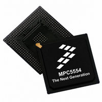
MPC5554INT Freescale Semiconductor, MPC5554INT Datasheet - Page 8

MPC5554INT
Manufacturer Part Number
MPC5554INT
Description
BOARD DEMO MPC5554
Manufacturer
Freescale Semiconductor
Type
MCUr
Datasheet
1.MPC5554INT.pdf
(54 pages)
Specifications of MPC5554INT
Contents
*
For Use With/related Products
MPC5554
Lead Free Status / RoHS Status
Lead free / RoHS Compliant
Electrical Characteristics
The thermal characterization parameter is measured in compliance with the JESD51-2 specification using
a 40-gauge type T thermocouple epoxied to the top center of the package case. Position the thermocouple
so that the thermocouple junction rests on the package. Place a small amount of epoxy on the thermocouple
junction and approximately 1 mm of wire extending from the junction. Place the thermocouple wire flat
against the package case to avoid measurement errors caused by the cooling effects of the thermocouple
wire.
References:
Semiconductor Equipment and Materials International
3081 Zanker Rd.
San Jose, CA., 95134
(408) 943-6900
MIL-SPEC and EIA/JESD (JEDEC) specifications are available from Global Engineering Documents at
800-854-7179 or 303-397-7956.
JEDEC specifications are available on the web at http://www.jedec.org.
1. C.E. Triplett and B. Joiner, “An Experimental Characterization of a 272 PBGA Within an Automotive
2. G. Kromann, S. Shidore, and S. Addison, “Thermal Modeling of a PBGA for Air-Cooled Applica-
3. B. Joiner and V. Adams, “Measurement and Simulation of Junction to Board Thermal Resistance and
3.3
The MPC5554 is available in packaged form. Read the package options in
Information.”
3.4
1
2
3
8
Spec
EMI testing and I/O port waveforms per SAE J1752/3 issued 1995-03. Qualification testing was performed on the MPC5554
and applied to the MPC5500 family as generic EMI performance data.
Measured with the single-chip EMI program.
Measured with the expanded EMI program.
1
2
3
4
5
6
7
Engine Controller Module,” Proceedings of SemiTherm, San Diego, 1998, pp. 47–54.
tions,” Electronic Packaging and Production, pp. 53–58, March 1998.
Its Application in Thermal Modeling,” Proceedings of SemiTherm, San Diego, 1999, pp. 212–220.
Scan range
Operating frequency
V
V
V
Maximum amplitude
Operating temperature
DD
DDSYN
PP
, V
Package
EMI (Electromagnetic Interference) Characteristics
operating voltages
DDEH
, V
Refer to
RC33
, V
DDA
, V
DD33
operating voltages
Section 4, “Mechanicals,”
Characteristic
, V
FLASH
, V
MPC5554 Microcontroller Data Sheet, Rev. 3.0
Table 4. EMI Testing Specifications
DDE
operating voltages
for pinouts and package drawings.
Minimum
0.15
—
—
—
—
—
—
1
Typical
1.5
3.3
5.0
—
—
—
—
Section 2, “Ordering
Freescale Semiconductor
Maximum
1000
f
14
32
MAX
—
—
25
—
2
3
dBuV
MHz
MHz
Unit
o
V
V
V
C


