MAXQ2000-KIT Maxim Integrated Products, MAXQ2000-KIT Datasheet
MAXQ2000-KIT
Specifications of MAXQ2000-KIT


Related parts for MAXQ2000-KIT


MAXQ2000-KIT Summary of contents
Page 1
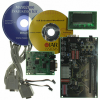
... MAXQ2000 LCD Display Daughterboard ♦ MAXQ2000 Evaluation Kit CD-ROM Ordering Information PART DESCRIPTION MAXQ2000-KIT MAXQ2000 EV Kit Board MAXQ is a registered trademark of Maxim Integrated Products, Inc. 1-Wire is a registered trademark of Dallas Semiconductor Corp. SPI is a trademark of Motorola, Inc. For pricing, delivery, and ordering information, please contact Maxim Direct at 1-888-629-4642, or visit Maxim’ ...
Page 2
... DIP switches x 8 SW2, SW4, SW5 3 SPST N/O pushbutton TP1—TP4 0.100” spaced test points U1, U2 MAX1658 350mA linear regulator U4 1 MAXQ2000 low-power LCD micro U5 1 DS1077L 3V EconOscillator™ MAX3387E 3V RS-232 transceiver U7 1 DS2433 4kB 1-Wire EEPROM U8 1 MAX1407 16-bit multi-ADC/DAC ...
Page 3
... MAXQ2000 EV kit board and does not require its own power supply. Two different types of power supplies (which are not included with the MAXQ2000 EV kit) are required to set up the configurations listed below. • 5V, ±5% 300mA DC regulated supply (25mm, center-post, positive female connector) to power the serial-to-JTAG interface board ...
Page 4
... JU3 JU3 Pins 1 and 2 connected JU3 Pins 2 and 3 connected * Refer to the MAXQ2000 data sheet for the allowable range of the V DD supply. 4 _____________________________________________________________________ To use the LCD daughterboard, it should be installed on the J3 connector of the MAXQ2000 EV kit board. Pin should line up with pin 1 of the LCD daughter- board J1 connector ...
Page 5
... No effect Note 1: If both SW6 #2 and #3 are closed, P5.2 and P5.3 will be shorted together. Note 2: If both SW6 #4 and #5 are closed, P7.0 and P7.1 will be shorted together. MAXQ2000 Evaluation Kit HFXIN is connected to HFXADJ P6.0 is connected to DS1077 SCL P6.1 is connected to DS1077 SDA ...
Page 6
... MAXQ2000 Evaluation Kit Figure 1. MAXQ2000 Evaluation Kit Setup SERIAL WINDOWS (COM) PC PORT RS-232 INTERFACE Figure 2. MAXQ2000 Serial-to-JTAG Interface 6 _____________________________________________________________________ TEST MODE SELECT TEST CLOCK SERIAL-TO-JTAG INTERFACE TEST DATA IN ADAPTER TEST DATA OUT JTAG/TAP INTERFACE MAXQ2000 ...
Page 7
... Figure 3. MAXQ2000 Evaluation Kit Functional Layout Figure 4. LCD Daughterboard Display Memory Mapping MAXQ2000 Evaluation Kit _____________________________________________________________________ 7 ...
Page 8
... MAXQ2000 Evaluation Kit Figure 5. MAXQ2000 Evaluation Kit Power Schematics—Power ( _____________________________________________________________________ ...
Page 9
... P04_SEG4 P04 62 P05_SEG5 P05 63 P06_SEG6 P06 64 P07_SEG7 P07 65 P10_SEG8 P10 66 P11_SEG9 P11 67 P12_SEG10 P12 68 Figure 5. MAXQ2000 Evaluation Kit Power Schematics—Processor ( MAXQ2000 Evaluation Kit RESET P43_TDO P42_TMS P41_TDI P40_TCK COM10 COM1_SEG35 COM2_SEG34 COM3_SEG33 SEG32 P37_SEG31 P36_SEG30 P35_SEG29 P34_SEG28 _____________________________________________________________________ 33 32 P43 31 ...
Page 10
... MAXQ2000 Evaluation Kit Figure 5. MAXQ2000 Evaluation Kit Power Schematics—ICE Interface/Header ( ____________________________________________________________________ ...
Page 11
... Figure 5. MAXQ2000 Evaluation Kit Power Schematics—LCD/Clock/JTAG ( MAXQ2000 Evaluation Kit ____________________________________________________________________ 11 ...
Page 12
... MAXQ2000 Evaluation Kit Figure 5. MAXQ2000 Evaluation Kit Power Schematics—Serial/1-Wire ( ____________________________________________________________________ ...
Page 13
... Figure 5. MAXQ2000 Evaluation Kit Power Schematics—MAX1407 ( MAXQ2000 Evaluation Kit ____________________________________________________________________ 13 ...
Page 14
... MAXQ2000 Evaluation Kit Figure 6. MAXQ2000 Evaluation Kit LCD Daughterboard Schematic 14 ____________________________________________________________________ ...
Page 15
... Figure 7. MAXQ2000 Evaluation Kit JTAG Board Schematic Maxim cannot assume responsibility for use of any circuitry other than circuitry entirely embodied in a Maxim product. No circuit patent licenses are implied. Maxim reserves the right to change the circuitry and specifications without notice at any time. ...