AT18F-DK3 Atmel, AT18F-DK3 Datasheet - Page 9
AT18F-DK3
Manufacturer Part Number
AT18F-DK3
Description
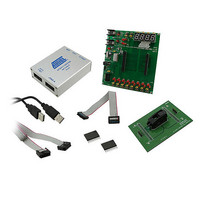
KIT CONFIG PROGRAM FOR AT18F FAM
Manufacturer
Atmel
Series
AT18Fr
Type
In-Circuit Emulator Systemr
Datasheet
1.ATF15XXDK3-SAX20.pdf
(22 pages)
Specifications of AT18F-DK3
Contents
2 Boards, Cable, CD, Samples
Processor To Be Evaluated
AT18F
Processor Series
AT18F
Interface Type
ISP, JTAG
Operating Supply Voltage
3.3 V
For Use With/related Products
AT18F Series
Lead Free Status / RoHS Status
Lead free / RoHS Compliant
Other names
Q4623814


3685A–CNFG–04/08
Hardware Description
2.1.3
2.1.4
2-4
Push-button Switches with Selectable Jumpers for I/O Pins
Push-button Switches with Selectable Jumpers for GCLR and OE1 Pins
Eight push-button switches with selectable jumpers are shown on the ATF15xx-DK3 Base Board of the
AT18F-DK3 kit. However, these components were designed for other Atmel adapter boards such us the
ATF15xx Series CPLDs and they are not intended to be used with ATF15xxDK3-SAX20 socket adapter
for AT18F Series Configurators. Therefore, there is no detailed description about these components in
this user guide, if you need additional information, see the ATF15xx-DK3 Kit user guide.
Figure 2-4.
Two push-button switches for the Global Clear (GCLR) and Output Enable (OE1) with selectable jump-
ers are shown on the ATF15xx-DK3 Base Board of the AT18F-DK3 kit. However, these components
were designed for other Atmel adapter boards such us the ATF15xx Series CPLDs and they are not
intended to be use with ATF15xxDK3-SAX20 socket adapter for AT18F Series Configurators. Therefore,
there is no detailed description about these components in this user guide, if you need additional infor-
mation, see the ATF15xx-DK3 Kit user guide.
Figure 2-5.
Circuit Diagram of the Push-button Switches and Jumpers for the I/O Pins
Circuit Diagram of Push-button Switches and Selectable Jumpers for GCLR and OE1
AT18F-DK3 Configurator Development Kit User Guide
Related parts for AT18F-DK3
Image
Part Number
Description
Manufacturer
Datasheet
Request
R

Part Number:
Description:
ACCY USB CABLE JTAG ISP AT18F
Manufacturer:
Atmel
Datasheet:

Part Number:
Description:
DEV KIT FOR AVR/AVR32
Manufacturer:
Atmel
Datasheet:

Part Number:
Description:
INTERVAL AND WIPE/WASH WIPER CONTROL IC WITH DELAY
Manufacturer:
ATMEL Corporation
Datasheet:
Part Number:
Description:
Low-Voltage Voice-Switched IC for Hands-Free Operation
Manufacturer:
ATMEL Corporation
Datasheet:
Part Number:
Description:
MONOLITHIC INTEGRATED FEATUREPHONE CIRCUIT
Manufacturer:
ATMEL Corporation
Datasheet:
Part Number:
Description:
AM-FM Receiver IC U4255BM-M
Manufacturer:
ATMEL Corporation
Datasheet:
Part Number:
Description:
Monolithic Integrated Feature Phone Circuit
Manufacturer:
ATMEL Corporation
Datasheet:
Part Number:
Description:
Multistandard Video-IF and Quasi Parallel Sound Processing
Manufacturer:
ATMEL Corporation
Datasheet:
Part Number:
Description:
High-performance EE PLD
Manufacturer:
ATMEL Corporation
Datasheet:
Part Number:
Description:
8-bit Flash Microcontroller
Manufacturer:
ATMEL Corporation
Datasheet:
Part Number:
Description:
2-Wire Serial EEPROM
Manufacturer:
ATMEL Corporation
Datasheet: