EPSILON5-A1 Equinox Technologies, EPSILON5-A1 Datasheet - Page 72
EPSILON5-A1
Manufacturer Part Number
EPSILON5-A1
Description
ISP PORTABLE PROGRAMMER USB
Manufacturer
Equinox Technologies
Series
Epsilon5r
Type
Portable ISPr
Specifications of EPSILON5-A1
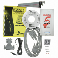
Contents
Programmer, Software, Cables and Documentation
Ic Product Type
In-Circuit Programmer
Features
2Mbits Of On-Board Non-Volatile FLASH Memory For User Project Storage
Interface Type
JTAG
Mcu Supported Families
ATmega And AT91SAM7
Mpu Supported Families
AVR
Rohs Compliant
Yes
External Depth
31mm
Height
189mm
Length
80mm
For Use With/related Products
ATMEL AT89S, AVR, AT91SAM7, NXP P89C51Rx2 P89C66x, Zensys, Serial EEPROM's
Other names
483-1000


4.4 J3 - Atmel 6-way ISP Header (SPI Interface)
This connection method is suitable for interfacing the EPSILON5 programmer to a Target System
which features the following:
The 6-way IDC box header is the most compact header i.e. takes up least space on the Target
System and so is very popular for designs where PCB space is limited. Unfortunately, this connection
method does not have any pins spare for extra functionality such as the SCK2 Oscillator so it should
only be used if this functionality is not required.
To implement this connection method, simply plug a 6-way ISP cable (not supplied) into the
EPSILON5 ISP Header J3 and plug the other end of the cable into the matching header on the
Target System.
Pin
No
1
2
3
4
5
EPSILON5 MKII Programmer - User Guide V1.10 – 10th July 2006
•
•
Programmer
Pin name
PROG_MISO
PROG_VCC
PROG_SCK1
PROG_MOSI
PROG_RESET O
Atmel 6-way IDC ISP Header
An Atmel device which features the 3-wire SPI + RESET Programming Interface
Programmer
Input /
Output
I
P
O
O
Connect to
pin on
Target Device
MISO
(except for
ATmega103/128/64
– connect to TXD
pin instead)
TARGET_VCC
SCK
MOSI
(except for
ATmega103/128/64
– connect to RXD
pin instead)
RESET
Figure 4.4.1 - Atmel 6-way IDC Header (J3) viewed from above
Warning!
Connecting to the wrong ISP Header may cause catastrophic
damage to the Programmer & Target System
Description
Master In Slave Out
This is the SPI data input pin to the
programmer. This pin should be
connected to the MISO pin on the Target
Microcontroller.
Target Vcc
This pin should be connected to the
Target System Vcc. This voltage could be
used to power the programmer depending
on the settings of the power switch/jumper
on the programmer.
SPI Serial Clock Output
This is the SPI clock output signal.
Master Out Slave In
This is the SPI data output pin from the
programmer. This pin should be
connected to the MOSI pin on the Target
Microcontroller.
Target RESET control pin
61
Related parts for EPSILON5-A1
Image
Part Number
Description
Manufacturer
Datasheet
Request
R

Part Number:
Description:
CONVERTER KIT, COMMS, RS485
Manufacturer:
Equinox Technologies
Datasheet:

Part Number:
Description:
MOD PPM3 CONN-3 I/O ATMEGA JTAG
Manufacturer:
Equinox Technologies
Datasheet:

Part Number:
Description:
MODULE FOR PPM3-MK2 I/O DRIVER
Manufacturer:
Equinox Technologies
Datasheet:

Part Number:
Description:
MOD PPM3 SPECIAL FUNCTION DRIVER
Manufacturer:
Equinox Technologies

Part Number:
Description:
MODULE CONVERTER RS232 TO RS485
Manufacturer:
Equinox Technologies

Part Number:
Description:
MODULE CALCON FOR PPMS-MK2
Manufacturer:
Equinox Technologies
Datasheet:

Part Number:
Description:
ISP PORTABLE HS AVR JTAG USB
Manufacturer:
Equinox Technologies
Datasheet:

Part Number:
Description:
ISP PORTABLE HS AT91SAM7 USB
Manufacturer:
Equinox Technologies
Datasheet:

Part Number:
Description:
ISP PORTABLE USB AT91SAM7 UPGRAD
Manufacturer:
Equinox Technologies

Part Number:
Description:
PORTABLE PRODUCTION ISP HS USB
Manufacturer:
Equinox Technologies
Datasheet:

Part Number:
Description:
ISP MULTI PROJECT AVR JTAG USB
Manufacturer:
Equinox Technologies
Datasheet:

Part Number:
Description:
ISP MULTI PROJECT AT91SAM7 USB
Manufacturer:
Equinox Technologies
Datasheet:

Part Number:
Description:
ISP PRODUCTION PROGRAMMER
Manufacturer:
Equinox Technologies
Datasheet:

Part Number:
Description:
ISP PORTABLE AVR JTAG UPGRAD
Manufacturer:
Equinox Technologies
Datasheet:

Part Number:
Description:
PROGRAMMER PORTABLE HI-SPEED ISP
Manufacturer:
Equinox Technologies