ADZS-HPUSB-ICE Analog Devices Inc, ADZS-HPUSB-ICE Datasheet - Page 34
ADZS-HPUSB-ICE
Manufacturer Part Number
ADZS-HPUSB-ICE
Description
TOOL EMULATOR USB HP CROSSCORE
Manufacturer
Analog Devices Inc
Type
In-Circuit Emulator Systemr
Specifications of ADZS-HPUSB-ICE
Contents
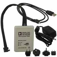
HPUSB-ICE, JTAG Pod, Power Supply and Cable
Silicon Family Name
Blackfin
Core Architecture
Blackfin
Ic Product Type
Emulator
Kit Contents
USB-based Emulator W/ 14-pin JTAG Connector, USB Cable
Features
USB 2.0, Up To 1.5MB/sec
Peak Reflow Compatible (260 C)
Yes
Rohs Compliant
Yes
Lead Free Status / RoHS Status
Lead free / RoHS Compliant
For Use With/related Products
ADSP-219x Blackfin®, SHARC® and TigerSHARC® DSPs
Lead Free Status / RoHS Status
Lead free / RoHS Compliant, Lead free / RoHS Compliant
Other names
ADZU-HPUSB-ICE
ADZU-HPUSB-ICE
ADZU-HPUSB-ICE
Available stocks
Company
Part Number
Manufacturer
Quantity
Price
Company:

Part Number:
ADZS-HPUSB-ICE
Manufacturer:
Analog Devices Inc
Quantity:
135
Part Number:
ADZS-HPUSB-ICE
Manufacturer:
ADI/亚德诺
Quantity:
20 000


Designing Custom Processor Boards
MSP430-ICE LED
Designing Custom Processor Boards
2-4
There is one LED located on the enclosure.
ENABLE – This LED is turned on when a VisualDSP++ debug session is
running. The LED shuts off every time the VisualDSP++ session is closed.
When this LED is off, it signifies all outputs of the pod logic connected to
the target have been three-stated. Three-stating the outputs of the pod
when VisualDSP++ is inactive prevents the target processor from entering
an unknown state during the target power up sequencing.
When designing a custom processor board using Analog Devices
processors and DSPs, special care must be taken to ensure that the JTAG
interface is designed and laid out correctly. If the board is not designed
correctly, communication via the JTAG port may not work. Another side
effect may be that the interface works, but you are not able to run at the
highest possible JTAG clock frequency. The JTAG clock frequency is
dependant on the particular Analog Devices processor, as well as the delay
characteristics of the custom processor board.
• VCC – This LED signifies that the board is receiving 5V power. If
• 3V – This LED signifies that the board is receiving 3.3V power. If
• FPGA[1:0] – These two LEDs are used for factory purposes only.
• DONE – This LED is activated when a VisualDSP++ debug ses-
this LED is not active, the HPPCI-ICE does not function properly.
this LED is not active, the HPPCI-ICE does not function properly.
sion is started. The LED should remain active even after the
respective session has been terminated. The LED shuts off and
re-activates at the beginning of every new VisualDSP++ session.
HPUSB, USB, HPPCI and MSP430 Emulators User’s Guide
Related parts for ADZS-HPUSB-ICE
Image
Part Number
Description
Manufacturer
Datasheet
Request
R

Part Number:
Description:
±1.7g Dual-Axis IMEMS Accelerometer Evaluation Board
Manufacturer:
Analog Devices Inc
Datasheet:

Part Number:
Description:
Inertial Sensor Evaluation System
Manufacturer:
Analog Devices Inc
Datasheet:
Part Number:
Description:
Manufacturer:
Analog Devices Inc
Datasheet:
Part Number:
Description:
Manufacturer:
Analog Devices Inc
Datasheet:
Part Number:
Description:
Manufacturer:
Analog Devices Inc
Datasheet:
Part Number:
Description:
Manufacturer:
Analog Devices Inc
Datasheet:
Part Number:
Description:
Manufacturer:
Analog Devices Inc
Datasheet:
Part Number:
Description:
Manufacturer:
Analog Devices Inc
Datasheet:
Part Number:
Description:
Manufacturer:
Analog Devices Inc
Datasheet:
Part Number:
Description:
Manufacturer:
Analog Devices Inc
Datasheet:
Part Number:
Description:
Manufacturer:
Analog Devices Inc
Datasheet:
Part Number:
Description:
Manufacturer:
Analog Devices Inc
Datasheet:
Part Number:
Description:
Manufacturer:
Analog Devices Inc
Datasheet: