NBSG111BAEVB ON Semiconductor, NBSG111BAEVB Datasheet - Page 8
NBSG111BAEVB
Manufacturer Part Number
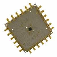
NBSG111BAEVB
Description
BOARD EVALUATION BBG NBSG111BA
Manufacturer
ON Semiconductor
Specifications of NBSG111BAEVB
Main Purpose
Clock/Data Driver
Utilized Ic / Part
NBSG111
Primary Attributes
W/RSECL Outputs
Technology Type
Evaluation Board
Lead Free Status / RoHS Status
Contains lead / RoHS non-compliant
For Use With/related Products
NBSG111
Other names
NBSG111BAEVB
NBSG111BAEVBOS
NBSG111BAEVBOS


NOTE: Device will meet the specifications after thermal equilibrium has been established when mounted in a test socket or printed circuit
12. Input and output parameters vary 1:1 with V
13. All outputs loaded with 50 W to V
14. V
15. V
16. V
17. V
*Typicals used for testing purposes.
Table 8. DC CHARACTERISTICS, NECL OR RSNECL INPUT WITH NECL OUTPUT
V
Symbol
I
VOH
V
V
V
V
V
V
R
I
I
EE
IH
IL
CC
OUTPP
IH
IL
BB
IHCMR
MM
TIN
input signal.
IHCMR
THR
IH
IL
= 0 V; V
always w V
cannot exceed V
board with maintained transverse airflow greater than 500 lfpm. Electrical parameters are guaranteed only over the declared
operating temperature range. Functional operation of the device exceeding these conditions is not implied. Device specification limit
values are applied individually under normal operating conditions and not valid simultaneously.
is the voltage applied to the complementary input, typically V
min varies 1:1 with V
Negative Power Supply Current
Output HIGH Voltage (Note 13)
Output Voltage Amplitude
Input HIGH Voltage
(Single−Ended) (Notes 15 and 16)
Input LOW Voltage
(Single−Ended) (Notes 15 and 17)
NECL Output Voltage Reference
Input HIGH Voltage Common Mode
Range (Differential Configuration)
(Note 14)
LVCMOS Output Voltage Reference
Internal Input Termination Resistor
Input HIGH Current (@ V
Input LOW Current (@ V
EE
= −3.465 V to −2.375 V (Note 12)
EE
.
Characteristic
CC
.
EE
, V
(@ − 2.5 V
(@ − 3.3 V
CC
IHCMR
IL
IH
)
− 1.5 V. V
)
max varies 1:1 with V
EE
EE
CC
OH
)
)
.
/V
−1135
−1475
−1450
−1850
V
V
2500
+ 75
Min
305
OL
70
45
THR
IH
V
measured at V
−
EE
http://onsemi.com
+1.2
−40°C
−1400
−1250
−1650
V
1000*
V
1400*
−980
Typ
420
CC
CC
85
50
30
25
CC
−
−
. The V
BB
8
−1235
−1050
−1450
V
−885
Max
V
− 75
IH
110
545
100
100
or V
0.0
55
THR
CC
IHCMR
/V
IL
MM
(Typical).
. V
−1090
−1475
−1450
−1850
V
V
2500
range is referenced to the most positive side of the differential
+ 75
Min
305
70
45
THR
IH
THR(MIN)
V
−
EE
+1.2
−1400
−1250
−1650
V
1000*
V
1400*
25°C
−970
Typ
420
CC
CC
85
50
30
25
= V
−
−
IHCMR
−1235
−1050
−1450
V
−840
Max
− 75
V
545
100
100
110
0.0
THR
55
CC
+ 75 mV. V
−1065
−1475
−1450
−1850
V
V
2500
+ 75
Min
305
70
45
THR
IH
V
−
EE
THR(MAX)
+1.2
V
V
−1400
−1250
−1650
1000*
1400*
−940
70°C
Typ
420
CC
CC
85
50
30
25
−
−
= V
−1235
−1050
−1450
IHCMR
V
−815
Max
V
− 75
545
100
100
110
0.0
55
THR
CC
− 75 mV.
Unit
mA
mV
mV
mV
mV
mV
mV
mA
mA
W
V
Related parts for NBSG111BAEVB
Image
Part Number
Description
Manufacturer
Datasheet
Request
R

Part Number:
Description:
2.5v/3.3v Sige Differential 1 10 Clock/data Driver With Rsecl Outputs
Manufacturer:
ON Semiconductor
Datasheet:
Part Number:
Description:
ON Semiconductor [VOLTAGE REGULATOR]
Manufacturer:
ON Semiconductor
Datasheet:
Part Number:
Description:
357-036-542-201 CARDEDGE 36POS DL .156 BLK LOPRO
Manufacturer:
ON Semiconductor
Datasheet:
Part Number:
Description:
357-036-542-201 CARDEDGE 36POS DL .156 BLK LOPRO
Manufacturer:
ON Semiconductor
Datasheet:
Part Number:
Description:
357-036-542-201 CARDEDGE 36POS DL .156 BLK LOPRO
Manufacturer:
ON Semiconductor
Datasheet:
Part Number:
Description:
357-036-542-201 CARDEDGE 36POS DL .156 BLK LOPRO
Manufacturer:
ON Semiconductor
Datasheet:
Part Number:
Description:
357-036-542-201 CARDEDGE 36POS DL .156 BLK LOPRO
Manufacturer:
ON Semiconductor
Datasheet:
Part Number:
Description:
357-036-542-201 CARDEDGE 36POS DL .156 BLK LOPRO
Manufacturer:
ON Semiconductor
Datasheet:
Part Number:
Description:
357-036-542-201 CARDEDGE 36POS DL .156 BLK LOPRO
Manufacturer:
ON Semiconductor
Datasheet:
Part Number:
Description:
357-036-542-201 CARDEDGE 36POS DL .156 BLK LOPRO
Manufacturer:
ON Semiconductor
Datasheet:
Part Number:
Description:
357-036-542-201 CARDEDGE 36POS DL .156 BLK LOPRO
Manufacturer:
ON Semiconductor
Datasheet:
Part Number:
Description:
357-036-542-201 CARDEDGE 36POS DL .156 BLK LOPRO
Manufacturer:
ON Semiconductor
Datasheet:
Part Number:
Description:
Manufacturer:
ON Semiconductor
Datasheet:
Part Number:
Description:
Manufacturer:
ON Semiconductor
Datasheet: