NLSF595EVB ON Semiconductor, NLSF595EVB Datasheet
NLSF595EVB
Manufacturer Part Number
NLSF595EVB
Description
BOARD EVAL TRICOLOR LED DRIVER
Manufacturer
ON Semiconductor
Specifications of NLSF595EVB
Design Resources
NLSF595 Demo Board BOM NLSF595EVB Gerber Files
Lead Free Status / RoHS Status
Contains lead / RoHS non-compliant
For Use With/related Products
NLSF595
Other names
NLSF595EVB
NLSF595EVBOS
NLSF595EVBOS
h
9/9/2003
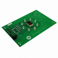
Thank you for your interest in the ON Semiconductor NLSF595 LED Driver Demo
board. This board demonstrates the use of the NLSF595 device with 8 individual red,
white, blue, and green LEDs and a 7 segment LED.
Note: The NLSF595 is controlled by the 12F629 PIC which is programmed prior to
Note: If you are using your own power source, be sure that the center pin supplies
Test Procedure for the NLSF595 LED Driver Demonstration Board
1.
2.
arrival.
positive voltage as many of the wall type power supplies have a negative center
pin.
Apply power by plugging the dc power source capable of 9 volts into J2 .
Observed Functionality:
a. Upon applying power, all individual LEDs including the 7 segment LED
b. The individual LEDs will advance through three levels of brightness.
c. The 7 segment LED will than read the number 1 simultaneously the
d. The LEDs will all flash simultaneously
e.
f. The 7 segment LED will display the number “8”
g. The sequence repeat incrementing the 7 segment LED from 2 through 0.
NLSF595 Demo Board
centered on the board will light up. The 7 segment unit will display an 8
individual LEDs will illuminate in a clockwise and counter clockwise
manner around the seven segment LED respectively.
Once the number “0” is reached the sequence starts again from 1.
All Leds will power off.
Table 1: Required Test Equipment
DC Power Source Capable of 9
Volts providing a current of .8 Amps
Related parts for NLSF595EVB
Image
Part Number
Description
Manufacturer
Datasheet
Request
R

Part Number:
Description:
Tri-color Led Driver
Manufacturer:
ON Semiconductor
Datasheet:

Part Number:
Description:
Buffers & Line Drivers 2-5.5V Quad Bus
Manufacturer:
ON Semiconductor
Datasheet:
Part Number:
Description:
ON Semiconductor [VOLTAGE REGULATOR]
Manufacturer:
ON Semiconductor
Datasheet:
Part Number:
Description:
357-036-542-201 CARDEDGE 36POS DL .156 BLK LOPRO
Manufacturer:
ON Semiconductor
Datasheet:
Part Number:
Description:
357-036-542-201 CARDEDGE 36POS DL .156 BLK LOPRO
Manufacturer:
ON Semiconductor
Datasheet:
Part Number:
Description:
357-036-542-201 CARDEDGE 36POS DL .156 BLK LOPRO
Manufacturer:
ON Semiconductor
Datasheet:
Part Number:
Description:
357-036-542-201 CARDEDGE 36POS DL .156 BLK LOPRO
Manufacturer:
ON Semiconductor
Datasheet:
Part Number:
Description:
357-036-542-201 CARDEDGE 36POS DL .156 BLK LOPRO
Manufacturer:
ON Semiconductor
Datasheet:
Part Number:
Description:
357-036-542-201 CARDEDGE 36POS DL .156 BLK LOPRO
Manufacturer:
ON Semiconductor
Datasheet:
Part Number:
Description:
357-036-542-201 CARDEDGE 36POS DL .156 BLK LOPRO
Manufacturer:
ON Semiconductor
Datasheet:
Part Number:
Description:
357-036-542-201 CARDEDGE 36POS DL .156 BLK LOPRO
Manufacturer:
ON Semiconductor
Datasheet:
Part Number:
Description:
357-036-542-201 CARDEDGE 36POS DL .156 BLK LOPRO
Manufacturer:
ON Semiconductor
Datasheet:
Part Number:
Description:
357-036-542-201 CARDEDGE 36POS DL .156 BLK LOPRO
Manufacturer:
ON Semiconductor
Datasheet:
Part Number:
Description:
Manufacturer:
ON Semiconductor
Datasheet: