DM163010 Microchip Technology, DM163010 Datasheet - Page 18
DM163010
Manufacturer Part Number
DM163010
Description
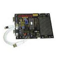
BOARD DEMO PICDEM USB
Manufacturer
Microchip Technology
Datasheet
1.DM163010.pdf
(80 pages)
Specifications of DM163010
Processor To Be Evaluated
PlC16C745/765
Interface Type
USB
Lead Free Status / RoHS Status
Lead free / RoHS Compliant
Lead Free Status / RoHS Status
Lead free / RoHS Compliant, Lead free / RoHS Compliant


PICDEM™ USB User’s Guide
DS41174A-page 14
2.1.2
2.1.3
About the PC Gameport
The PC gameport was designed to support 2 joysticks. Each joystick was
Hardware Implementation
The hardware is supplied on the PICDEM™ USB circuit board. The board is
intended to have 2 axis and 2 buttons. The gameport was later extended to
support a MIDI serial interface. The gameport hardware supplied with the
PICDEM™ USB does not support the MIDI interface, so those pins have
been disconnected. Two joysticks are supported, but to simplify the example,
only one joystick is used.
wired with PORTA<3:0> and PORTD<3:0>, connected to the DB-15 connec-
tor of the gameport. PORTD<3:0> are the digital inputs for buttons A-D.
PORTA<0> and PORTA<1> are the X-Y inputs for the D-pad on the game-
pad. PORTA<2> and PORTA<3> are the inputs for buttons E and F (see
Appendix A for the gamepad to PICDEM™ USB schematic). All of the analog
pins have a series resistor, a resistor, and capacitor tied to ground. The rea-
son for this comes from the way analog pins were originally read by the PC.
The PC would clear a capacitor tied to ground at its end and then time how
long it took the capacitor to charge up. The capacitor would charge at a rate
proportional to the resistance of a pot, varied by one axis of the joystick, for
instance. This is legacy technology and is not needed when using a PICmicro
MCU with an analog-to-digital converter. As a result, the before mentioned
circuitry was put into place in order to obtain an analog output from the D-pad
of the gamepad and buttons E and F. Another point of confusion develops
from viewing the analog output of the gamepad with this circuitry in place. The
Note:
Although the Dexxa
ates as a 6-button gamepad. This is due to the gamepad having
two “special” buttons, that rapidly fire two of the other button
outputs.
TA
Figure 2.1: Dexxa
D-
PAD
®
gamepad has 8 buttons, the code enumer-
C
®
A
Gamepad
B
©
2001 Microchip Technology Inc.
TB
D
F
E
Related parts for DM163010
Image
Part Number
Description
Manufacturer
Datasheet
Request
R

Part Number:
Description:
Manufacturer:
Microchip Technology Inc.
Datasheet:
Part Number:
Description:
Manufacturer:
Microchip Technology Inc.
Datasheet:
Part Number:
Description:
Manufacturer:
Microchip Technology Inc.
Datasheet:
Part Number:
Description:
Manufacturer:
Microchip Technology Inc.
Datasheet:
Part Number:
Description:
Manufacturer:
Microchip Technology Inc.
Datasheet:
Part Number:
Description:
Manufacturer:
Microchip Technology Inc.
Datasheet:
Part Number:
Description:
Manufacturer:
Microchip Technology Inc.
Datasheet:
Part Number:
Description:
Manufacturer:
Microchip Technology Inc.
Datasheet: