DM163010 Microchip Technology, DM163010 Datasheet - Page 45
DM163010
Manufacturer Part Number
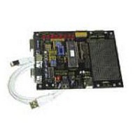
DM163010
Description
BOARD DEMO PICDEM USB
Manufacturer
Microchip Technology
Datasheet
1.DM163010.pdf
(80 pages)
Specifications of DM163010
Processor To Be Evaluated
PlC16C745/765
Interface Type
USB
Lead Free Status / RoHS Status
Lead free / RoHS Compliant
Lead Free Status / RoHS Status
Lead free / RoHS Compliant, Lead free / RoHS Compliant


4.4
©
2001 Microchip Technology Inc.
File Packaging
4.3.5
4.3.6
Common RAM Usage
The PIC16C745/765 has 16 bytes of common RAM. They are the last 16
addresses in each bank and all refer to the same 16 bytes of memory, without
regard to which register bank is currently addressed by the RP0, RP1 and IRP
bits.
They are particularly useful when responding to interrupts. When an interrupt
occurs, the ISR doesn’t immediately know which bank is addressed. With
devices that don’t support common RAM, the W register must be provided for
in each bank. The PIC16C745/765 can save the appropriate registers in Com-
mon RAM and not have to waste a byte in each bank for the W register.
Buffer Allocation
The PIC16C745/765 has 64 bytes of Dual Port RAM. Twenty-four bytes are
used for the Buffer Descriptor Table (BDT), leaving 40 bytes for buffers.
Endpoint 0 (EP0) IN and OUT need dedicated buffers, since a setup transac-
tion can never be NAKed. That leaves three buffers for four possible end-
points. However, the USB Spec. requires that low speed devices are only
allowed 2 endpoints (USB V1.1, paragraph 5.3.1.2), where an endpoint is a
simplex connection that is defined by the combination of endpoint number and
direction.
The default configuration allocates individual buffers to EP0 OUT, EP0 IN,
EP1 OUT, and EP1 IN. The last buffer is shared between EP2 IN and EP2
OUT. Again, the USB Spec. states that low speed devices can only use two
endpoints beyond EP0. This configuration supports most of the possible com-
binations of endpoints (EP1 OUT and EP1 IN, EP1 OUT and EP2 IN, EP1
OUT and EP2 OUT, EP1 IN and EP2 OUT, EP1 IN and EP2 IN). The only
combination that is not supported by this configuration is EP2 IN and EP2
OUT. If your application needs both EP2 IN and EP2 OUT, the function
USBReset will need to be edited to give each of these endpoints dedicated
buffers at the expense of EP1.
The software interface is packaged into four files, designed to simplify the
integration with your application.
File usb_ch9.asm contains the interface and core functions needed to enu-
merate the bus. File descript.asm contains the device, configuration, inter-
face, endpoint, and string descriptors. Both of these files must be linked in
with your application.
Chapter 9 USB Firmware
DS41174A-page 41
Related parts for DM163010
Image
Part Number
Description
Manufacturer
Datasheet
Request
R

Part Number:
Description:
Manufacturer:
Microchip Technology Inc.
Datasheet:
Part Number:
Description:
Manufacturer:
Microchip Technology Inc.
Datasheet:
Part Number:
Description:
Manufacturer:
Microchip Technology Inc.
Datasheet:
Part Number:
Description:
Manufacturer:
Microchip Technology Inc.
Datasheet:
Part Number:
Description:
Manufacturer:
Microchip Technology Inc.
Datasheet:
Part Number:
Description:
Manufacturer:
Microchip Technology Inc.
Datasheet:
Part Number:
Description:
Manufacturer:
Microchip Technology Inc.
Datasheet:
Part Number:
Description:
Manufacturer:
Microchip Technology Inc.
Datasheet: