EVAL-AD7731EB Analog Devices Inc, EVAL-AD7731EB Datasheet
EVAL-AD7731EB
Specifications of EVAL-AD7731EB


Related parts for EVAL-AD7731EB


EVAL-AD7731EB Summary of contents
Page 1
... ADC AD780 AV DD REFERENCE REF IN MCLK IN One Technology Way, P.O. Box 9106, Norwood. MA 02062-9106, U.S.A. Tel: 617/329-4700 Evaluation Board for Process Control ADC EVAL-AD7731EB and DGND. The AD7731 is specified DD of +5V. Therefore, the AV voltage supplied DD voltage is also used to DD and DV DD and DV ...
Page 2
... EVAL-AD7731EB LINK OPTIONS There are a number of link options on the evaluation board which should be set for the required operating setup before using the board. The functions of these link options are described in detail below. Link No. Function LK1 This option selects the master clock option for the AD7731. The master clock source comes from the on- board crystal or from an external clock source via SKT11 ...
Page 3
... The evaluation board should be powered up before a cable is connected to either of the connectors. SKT2 is used to connect the evaluation board to the printer port (parallel port PC. Connection between the two is direct via a standard parallel printer port cable. SKT1 is used to connect the evaluation board to any other system. REV. A EVAL-AD7731EB Figure 2 ...
Page 4
... EVAL-AD7731EB 18 36 Table III. SKT2 Pin Designations Connect. This pin is not connected on the evaluation board Serial Data Input. Data applied to this pin is buffered before being applied to the AD7731's DIN pin. The serial data applied to the DIN pin is written to the input shift register on the part. Data from this input shift register is transferred to one of the on-chip registers depending on the register selection bits of the Communications Register ...
Page 5
... MCLK IN input of the AD7731 is applied to this socket when the board is configured for an externally- applied master clock. REV. A EVAL-AD7731EB RUNNING THE AD7731 INTERFACE SOFTWARE Included in the evaluation board package is a PC-compatible disk which contains software for controlling and evaluating the performance of the AD7731 using the printer port ...
Page 6
... EVAL-AD7731EB Read from File Pressing this button allows the user to read data from a file for noise analysis. The data to be read can either be in decimal or hexadecimal format. Write to File This button allows the user to store of output data from the AD7731 to a file in either decimal or hexadecimal format. This data can be used in other programs or can subsequently be read back to the AD7731 software ...
Page 7
... REV. A Figure 5. Program Screen Figure 6. Mode Register Screen –7– EVAL-AD7731EB ...
Page 8
... EVAL-AD7731EB –8– REV. A ...
Page 9
... C16 C17 Philips Mftrs No. 683 34339 Location Vendor R10 R11 ---------- R5 Bourns Bourns R9 Bourns Location Vendor Lk1 (4x2 way) Harwin Lk2, Lk3,Lk4 (2x2 way) Mftrs No. M20-9993606 Lk5 (3x2 way) Lk6,Lk7,Lk8,Lk9,Lk10,Lk11 (1x2 way) Pin Headers (12 required) Harwin Mftrs No. M7571-05 –9– EVAL-AD7731EB ±5% 0.25W ...
Page 10
... EVAL-AD7731EB SWITCH Component Sealed Push Button Switch SOCKETS Component Miniature BNC Connectors 9-Way D-Type Connector 36 Way Centronics Connector 2 Way Terminal Block Low profile socket CRYSTAL OSCILLATOR Component Identification 4.9152 MHz Oscillator Location Vendor Omron Mftrs No. B3W1000 Location Vendor SKT3 - SKT11 M/A - Com Greenpar Mftrs No ...
Page 11
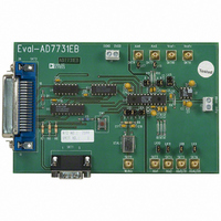
... REV. A Figure 8. Component Placement Diagram. –11– EVAL-AD7731EB ...