EVAL-ADT7470EB Analog Devices Inc, EVAL-ADT7470EB Datasheet - Page 29
EVAL-ADT7470EB
Manufacturer Part Number
EVAL-ADT7470EB
Description
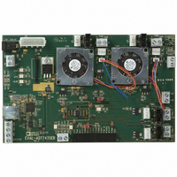
BOARD EVALUATION FOR ADT7470
Manufacturer
Analog Devices Inc
Datasheet
1.ADT7470ARQZ.pdf
(40 pages)
Specifications of EVAL-ADT7470EB
Sensor Type
Temperature
Interface
SMBus (2-Wire/I²C)
Voltage - Supply
3 V ~ 5.5 V
Embedded
No
Utilized Ic / Part
ADT7470
Lead Free Status / RoHS Status
Contains lead / RoHS non-compliant


DETAILED REGISTER DESCRIPTIONS
Table 24. Register 0x20 to Register 0x29. Temperature Reading Registers (Power-On Default = 0x00).
Register
Address
0x20
0x21
0x22
0x23
0x24
0x25
0x26
0x27
0x28
0x29
Readings from daisy-chained TMP05 are processed and loaded into the temperature reading registers.
Table 25. Register 0x2A to Register 0x31. Fan Tach Reading Registers (Power-On Default = 0x00).
Register Address
0x2A
0x2B
0x2C
0x2D
0x2E
0x2F
0x30
0x31
The fan tach reading registers shown in Table 25 count the number of 11.11 μs periods (based on an internal 90 kHz clock) that occur
between a number of consecutive fan tach pulses (default = 2). The number of tach pulses used to count can be changed using the fan
pulses per revolution register (Register 0x43). This allows the fan speed to be accurately measured. Because a valid fan tachometer
reading requires that two bytes are read, the low byte must be read first. Both the low and high bytes are then frozen until read. At power-
on, these registers contain 0x0000 until such time as the first valid fan tach measurement is read in to these registers. This prevents false
interrupts from occurring while the fans are spinning up.
A count of 0xFFFF indicates that a fan is
•
•
•
Table 26. Register 0x32 to Register 0x35. Current PWM Duty Cycle Registers (Power-On Default = 0xFF).
Register Address
0x32
0x33
0x34
0x35
The current PWM duty cycle registers, shown in Table 26, reflect the PWM duty cycle driving each fan at any given time. When in
automatic fan speed control mode, the ADT7470 reports the PWM duty cycles back through these registers. The PWM duty cycle values
vary according to temperature in automatic fan speed control mode. During fan startup, these registers report back 0x00. In manual fan
control mode, the PWM duty cycle outputs can be set to any duty cycle value by writing to these registers.
Stalled or blocked (object jamming the fan).
Failed (internal circuitry destroyed).
Not populated. The ADT7470 expects to see a fan connected to each tach. If a fan is not connected to that tach,
its tach minimum high and low byte are set to 0xFFFF.
Read/Write
Read-only
Read-only
Read-only
Read-only
Read-only
Read-only
Read-only
Read-only
Read-only
Read-only
Read/Write
Read-only
Read-only
Read-only
Read-only
Read-only
Read-only
Read-only
Read-only
Read/Write
Read/Write
Read/Write
Read/Write
Read/Write
Description
8-bit Temperature 1 reading (from TMP05 sensor).
8-bit Temperature 2 reading (from TMP05 sensor).
8-bit Temperature 3 reading (from TMP05 sensor).
8-bit Temperature 4 reading (from TMP05 sensor).
8-bit Temperature 5 reading (from TMP05 sensor).
8-bit Temperature 6 reading (from TMP05 sensor).
8-bit Temperature 2 reading (from TMP05 sensor).
8-bit Temperature 3 reading (from TMP05 sensor).
8-bit Temperature 4 reading (from TMP05 sensor).
8-bit Temperature 5 reading (from TMP05 sensor).
Description
PWM1 current duty cycle (0% to 100% duty cycle = 0x00 to 0xFF).
PWM2 current duty cycle (0% to 100% duty cycle = 0x00 to 0xFF).
PWM3 current duty cycle (0% to 100% duty cycle = 0x00 to 0xFF).
PWM4 current duty cycle (0% to 100% duty cycle = 0x00 to 0xFF).
Description
Tach 1 low byte (8 MSBs of reading).
Tach 1 high byte (8 LSBs of reading).
Tach 2 high byte (8 MSBs of reading).
Tach 2 low byte (8 LSBs of reading).
Tach 3 high byte (8 MSBs of reading).
Tach 3 low byte (8 LSBs of reading).
Tach 4 high byte (8 MSBs of reading).
Tach 4 low byte (8 LSBs of reading).
Rev. C | Page 29 of 40
Comments
Bit[7] = Sign bit, indicates if temperature is positive or
negative
Bits[6:0] = temperature result
To calculate the temperature:
Positive Temperature = ADC Code (decimal)
Negative Temperature = ADC (decimal) minus 256
ADT7470
Related parts for EVAL-ADT7470EB
Image
Part Number
Description
Manufacturer
Datasheet
Request
R


Part Number:
Description:
BOARD EVAL FOR SI270X-A
Manufacturer:
Silicon Laboratories Inc
Datasheet:

Part Number:
Description:
BUCK CONV REF DESIGN KIT IP1201
Manufacturer:
International Rectifier
Datasheet:
Part Number:
Description:
BOARD DEMO SYNC DUAL BUCK CNVTER
Manufacturer:
International Rectifier
Datasheet:
Part Number:
Description:
BOARD DEMO SYNC BUCK CONVETER
Manufacturer:
International Rectifier
Datasheet:

Part Number:
Description:
EVALBOARD/EB Omnidirectional microphone - Analog
Manufacturer:
Analog Devices
Datasheet:
Part Number:
Description:
EVALBOARD/EB Omnidirectional microphone - Analog
Manufacturer:
Analog Devices
Datasheet:


Part Number:
Description:
BOARD EVAL LED DRIVER LT3756
Manufacturer:
Linear Technology
Datasheet:

Part Number:
Description:
BOARD EVAL FOR AD7741/7742
Manufacturer:
Analog Devices Inc
Datasheet:

Part Number:
Description:
±1.7g Dual-Axis IMEMS Accelerometer Evaluation Board
Manufacturer:
Analog Devices Inc
Datasheet:

Part Number:
Description:
IC MULTIPLIER ANALOG 8-SOIC T/R
Manufacturer:
Analog Devices Inc
Datasheet:

Part Number:
Description:
IC ANALOG MULTIPLIER 8-DIP
Manufacturer:
Analog Devices Inc
Datasheet:
Part Number:
Description:
IC ANALOG MULTIPLIER 8-SOIC
Manufacturer:
Analog Devices Inc
Datasheet:
Part Number:
Description:
IC ANALOG MULTIPLIER 8-DIP
Manufacturer:
Analog Devices Inc
Datasheet: